STAAD.Pro Help

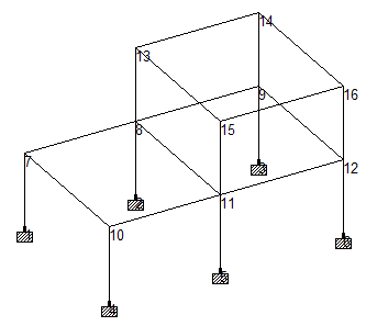
M. To cut a section of a model

The file US.8. Concrete Design for a Space Frame.STD is used to demonstrate this feature.

  1. (Optional) Press <Shift+N> to display the node numbers.

    This will aide in specifying a node number in the following step.

  2. Use the cut section tool:
    1. On the Utilities ribbon tab, select the Structure Tools tool in the Geometry Tools group.

    2. Select the Cut Section tool from the drop-down list.

    The Section dialog opens.

  3. Specify a cut plane by joint and plane orientation (range by joint method):
    1. Select the Range By Joint tab.
    2. Select the X - Z Plane option.
    3. Select 10 from the With Node # drop-down list (which contains all node numbers in the model).
      Tip: You can select any node with in this same plane to achieve the same result.
    4. Click OK.
  4. To restore the original view, select the Whole Structure tool in the Tools group on the View ribbon tab.

    Tip: Alternatively, you can click Show All on the Section dialog.
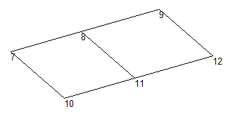
  5. Specify a cut plane by minimum and maximum distances and plane orientation (the range by min/max method):
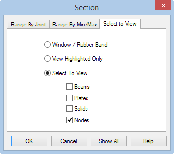
    1. Repeat step 2 to open the Section dialog.
    2. Select the Range By Min/Max tab.
    3. Select the X-Z Plane option.
    4. Type 10 in the Minimum field and type 14 in the Maximum field.

      The Minimum and Maximum values are the boundary distances along the axis perpendicular to the sectional plane. Every object lying entirely between these two distances will be displayed.

      Note: When using this method, make sure that the current input units of length are in the intended units.
  6. Repeat step 4 to restore original view.
  7. Display only the nodes for quick selection (the Select to View method):
    1. Select the Select To View tab.

    2. Select the Select To View option.
    3. Check the Node option.
    4. Click OK.

    The nodes only displayed for

  8. Select the Whole Structure tool to restore original view.
Note: You can save these views by selecting the View Management > Save View tool in the Views group on the View ribbon tab. Provide a title for the new view. These saved views may later be opened by selecting the Open View tool in the Views group on the View ribbon tab.