Deformation Parameters
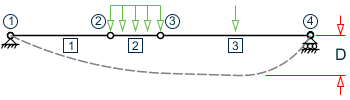
In the process of deflection inspection, various clauses in Appendix B of GB 50017-2017 are considered. If you need to consider the provisions of member deflection in the process of specification inspection and component selection, it can be controlled by three parameters DFF, DJ1, and DJ2. The DFF parameter takes the ratio of span to maximum allowable deformation as the limit value of deformation, which is called "deflection length". The "flexure length" is the length of the member used to calculate the local deformation between the two ends. In most cases, the length of the member is equal to the length of the member. However, in some special cases, the "flexural length" may be different from the member length. For example, the beam shown in the following figure has 4 nodes and 3 members (in this case, two nodes are added in the middle of the component). In this case, for all three beam members, the "flexural length" is defined as the total length of the beam. Parameters DJ1 and DJ2 can be used to define this situation. At the same time, the connecting line between DJ1 and DJ2 is also the reference line for measuring the local deflection of the rod. Therefore, for all three members, DJ1 should be node 1 and DJ2 should be node 4. If DJ1 and DJ2 are not defined, the default value of "flexural length" is the length of the member (DJ1 and DJ2 take the end node of the member respectively), and the local displacement will be calculated along the line (i.e. axis) of the two ends of the member.
The default setting value of the program is DFF = 400; DJ1 and DJ2 are the end nodes of components respectively. For DFF, you should take the denominator value of the corresponding type of allowable deflection in Appendix B according to the provisions of the code GB 50017-2017, and consider the provisions of other clauses.