V. ASCE 7-02 Wind Load Generation on Building
Verify the windward loads due to wind on a portion of a building structure calculated per the ASCE 7-02 specification.
Details
The wind load is calculated for a rigid building structure using the procedure for MWFRS of enclosed buildings (ASCE 7-02, Section 6.5.12.2.1). The following assumptions and parameters apply:
- Flat roof type
- Category II building (Table 1-1)
- Basic wind speed = 108 mph
- Structure type of "building"
- Exposure Category B
- Do not consider wind speed-up over hills or escarpments
- Building height = 40 ft
- Building length along the wind direction, L = 10 ft
- Building width normal to wind direction, B = 20 ft
- Natural frequency of structure = 2 Hz (i.e., a "rigid" building per Section 6.2)
- Damping ratio = 0.05
- Enclosed building (per Section 6.2)
Calculate the resulting joint loads on the windward side due to wind along the X axis at the upper wall of one segment of the building.

Building structure with wind load in X direction
Validation
Importance factor, I = 1.0 (Table 6-1)
The velocity pressure exposure coefficients (Kz) are calculated per the formulae given in Table 6-3:
| (Table 6-3) |
| = | ||
| = |
See the table below for the values of Kz at discrete values of z.
Directionality factor, Kd = 0.85 (Table 6-4)
Topographic factor, Kzt = 1.0 (i.e., not considered)
Velocity pressure, qz
| (Eq. 6-15) |
Mean roof height = height of the building = 30 ft. Refer to table below for calculation of qz at the mean roof height.
Gust effect factor, G
G is calculated per Cl. 26.11.4 for rigid structures:
| (Eq. 6-4) |
| = | ||
| = | ||
| = | ||
| = | ||
| = | ||
| = | ||
| = | ||
| = |
External pressure coefficient, Cp = 0.8 for windward per Fig. 6-6.
The external design pressure, p = qhGCp.
The internal pressure coefficient, GCpi = -0.18 for partially enclosed buildings per Figure 6-5.
The internal design pressure, pi = qi(GCpi) = 19.30 × -0.18 = -3.47 lb/ft2
where| = |
| p = qzGCp - qi(GCpi) | (Eq. 6-17) |
| h (ft) | Kz | qz
(lb/ft2) |
p (lb/ft2) |
|---|---|---|---|
| 0 | 0.575 | 14.59 | 13.61 |
| 15 | 0.575 | 14.59 | 13.61 |
| 20 | 0.624 | 15.84 | 14.48 |
| 25 | 0.665 | 16.88 | 15.20 |
| 30 | 0.701 | 17.78 | 15.83 |
| 35 | 0.732 | 18.58 | 16.38 |
| 40 | 0.761 | 19.30 | 16.89 |
Load on Nodes 1 and 9
Assume that the ground (Y = 0') acts as a bounded edge for the wind load acting on the exterior of the building. This edge transfers load to the columns.

Tributary area for nodes 1 and 9
Wind pressure at half-way between this node and level above (5') = 13.61 lb/ft2.
F = (10 ft / 2) × (10 ft / 2) × 13.61 lb/ft2 (10)-3 = 0.34 kips
Load on Node 5

Tributary area for node 5
F = (10 ft / 2) × (10 ft) × 13.60 lb/ft2 (10)-3 = 0.68 kips
Load on Nodes 2 and 10
Tributary area for nodes 2 and 10
F = (10 ft / 2) × (10 ft) × 13.61 lb/ft2 (10)-3 = 0.68 kips
Load on Node 6

Tributary area for node 6
F = (10 ft) × (10 ft ) × 13.61 lb/ft2 (10)-3 = 1.36 kips
Load on Nodes 13 and 17

Wind pressure at half-way between this node and level below (15') = 13.61 lb/ft2.
Wind pressure at half-way between this node and level above (25') = 15.20 lb/ft2.
F = (10 ft /2 ) × (10 ft / 2) × (13.61 lb/ft2 + 15.20 lb/ft2) (10)-3 = 0.72 kips
Load on Node 15
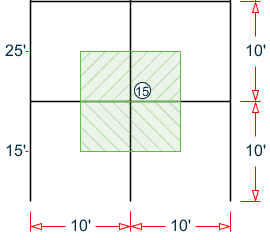
Wind pressure at half-way between this node and level below (15') = 13.61 lb/ft2.
Wind pressure at half-way between this node and level above (25') = 15.20 lb/ft2.
F = (10 ft /2 ) × (10 ft) × (13.61 lb/ft2 + 15.20 lb/ft2) (10)-3 = 1.44 kips
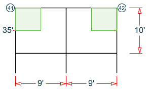
Load on Node 19

Tributary area for nodes 19 and 23
Wind pressure at half-way between this node and level below (25') = 15.20 lb/ft2.
Wind pressure at half-way between this node and level above (35') = 16.38 lb/ft2.
F = (10 ft /2 ) × (10 ft / 2) × (15.20 lb/ft2 + 16.38 lb/ft2) (10)-3 = 0.79 kips
Load on Node 21

Tributary area for node 21
Wind pressure at half-way between this node and level below (25') = 15.20 lb/ft2.
Wind pressure at half-way between this node and level above (35') = 16.38 lb/ft2.
F = (10 ft) × (10 ft / 2) × (15.20 lb/ft2 + 16.38 lb/ft2) (10)-3 = 1.58 kips
Load on Nodes 25 and 29

Wind pressure at roof level (40') = 16.89 lb/ft2.
F = (10 ft / 2) × (10 ft / 2) × 16.89 lb/ft2 (10)-3 = 0.42 kips

Results
| Result Type | Reference | STAAD.Pro | Difference | Comments |
|---|---|---|---|---|
| Node 1 | 0.34 | 0.34 | none | |
| Node 5 | 0.68 | 0.68 | none | |
| Node 2 | 0.68 | 0.68 | none | |
| Node 6 | 1.36 | 1.36 | none | |
| Node 13 | 0.72 | 0.73 | negligible | |
| Node 15 | 1.44 | 1.46 | negligible | |
| Node 19 | 0.79 | 0.80 | negligible | |
| Node 21 | 1.58 | 1.59 | negligible | |
| Node 25 | 0.42 | 0.42 | none | |
| Node 27 | 0.84 | 0.84 | none |
STAAD.Pro Input
The file C:\Users\Public\Public Documents\STAAD.Pro CONNECT Edition\Samples\ Verification Models\06 Loading\Wind Load\ASCE7-02 Wind Load Generation on Building.STD is typically installed with the program.
STAAD SPACE
START JOB INFORMATION
ENGINEER DATE 05-Sep-18
END JOB INFORMATION
INPUT WIDTH 79
UNIT FEET KIP
JOINT COORDINATES
1 0 0 0; 2 0 10 0; 3 10 10 0; 4 10 0 0; 5 0 0 10; 6 0 10 10; 7 10 10 10;
8 10 0 10; 9 0 0 20; 10 0 10 20; 11 10 10 20; 12 10 0 20; 13 0 20 0;
14 10 20 0; 15 0 20 10; 16 10 20 10; 17 0 20 20; 18 10 20 20; 19 0 30 0;
20 10 30 0; 21 0 30 10; 22 10 30 10; 23 0 30 20; 24 10 30 20; 25 0 40 0;
26 10 40 0; 27 0 40 10; 28 10 40 10; 29 0 40 20; 30 10 40 20;
MEMBER INCIDENCES
1 1 2; 2 2 3; 3 3 4; 4 2 6; 5 3 7; 6 5 6; 7 6 7; 8 7 8; 9 6 10; 10 7 11;
11 9 10; 12 10 11; 13 11 12; 14 2 13; 15 3 14; 16 6 15; 17 7 16; 18 10 17;
19 11 18; 20 13 14; 21 13 15; 22 14 16; 23 15 16; 24 15 17; 25 16 18; 26 17 18;
27 13 19; 28 14 20; 29 15 21; 30 16 22; 31 17 23; 32 18 24; 33 19 20; 34 19 21;
35 20 22; 36 21 22; 37 21 23; 38 22 24; 39 23 24; 40 19 25; 41 20 26; 42 21 27;
43 22 28; 44 23 29; 45 24 30; 46 25 26; 47 25 27; 48 26 28; 49 27 28; 50 27 29;
51 28 30; 52 29 30;
DEFINE MATERIAL START
ISOTROPIC STEEL_50_KSI
E 4.176e+06
POISSON 0.3
DENSITY 0.489024
ALPHA 6.5e-06
DAMP 0.03
TYPE STEEL
STRENGTH FY 7200 FU 8928 RY 1.5 RT 1.2
END DEFINE MATERIAL
MEMBER PROPERTY AMERICAN
1 TO 52 TABLE ST W14X873
CONSTANTS
MATERIAL STEEL_50_KSI ALL
SUPPORTS
1 4 5 8 9 12 FIXED
DEFINE WIND LOAD
TYPE 1 WIND 1
<! STAAD PRO GENERATED DATA DO NOT MODIFY !!!
ASCE-7-2002:PARAMS 108.000 mph 0 1 1 0 0.000 ft 30.000 ft 10.000 ft 1 2 -
40.000 ft 10.000 ft 20.000 ft 2.000 0.050 0 0 0 0 0 0.761 1.000 1.000 0.850 -
0 0 0 0 0.868 0.800 -0.180
!> END GENERATED DATA BLOCK
INT 0.0136076 0.0136076 0.0139629 0.0142904 0.0145949 0.0148798 0.015148 -
0.0154016 0.0156424 0.0158718 0.0160911 0.0163013 0.0165031 0.0166975 -
0.0168849 HEIG 0 15 16.9231 18.8461 20.7692 22.6923 24.6154 26.5385 28.4615 -
30.3846 32.3077 34.2308 36.1538 38.0769 40
EXP 1 JOINT 1 TO 12
LOAD 1 LOADTYPE Wind  TITLE LOAD CASE 1
WIND LOAD X 1 TYPE 1 YR 0 40
PERFORM ANALYSIS PRINT LOAD DATA
FINISH
STAAD.Pro Output
   LOADING     1  LOADTYPE WIND  TITLE LOAD CASE 1
   -----------
   JOINT LOAD - UNIT KIP  FEET
   JOINT   FORCE-X   FORCE-Y     FORCE-Z     MOM-X     MOM-Y     MOM-Z
       1      0.34      0.00        0.00      0.00      0.00      0.00
       2      0.68      0.00        0.00      0.00      0.00      0.00
       5      0.68      0.00        0.00      0.00      0.00      0.00
       6      1.36      0.00        0.00      0.00      0.00      0.00
       9      0.34      0.00        0.00      0.00      0.00      0.00
      10      0.68      0.00        0.00      0.00      0.00      0.00
      13      0.73      0.00        0.00      0.00      0.00      0.00
      15      1.46      0.00        0.00      0.00      0.00      0.00
      17      0.73      0.00        0.00      0.00      0.00      0.00
      19      0.80      0.00        0.00      0.00      0.00      0.00
      21      1.59      0.00        0.00      0.00      0.00      0.00
      23      0.80      0.00        0.00      0.00      0.00      0.00
      25      0.42      0.00        0.00      0.00      0.00      0.00
      27      0.84      0.00        0.00      0.00      0.00      0.00
      29      0.42      0.00        0.00      0.00      0.00      0.00