To perform the column design
- Either: The Failed Columns Dialog dialog opens indicating that two columns have failed the design checks.
- Click OK.
- Either: The Failure Diagnostics tab opens. The table indicates that the two beams have failed a detailing check.
-
Evaluate some options for column 12:
- Select the row for column C12 from 6m TO 12m in the column design table. This column is marked with a red tag to indicate it failed one or more checks.
-
Either:
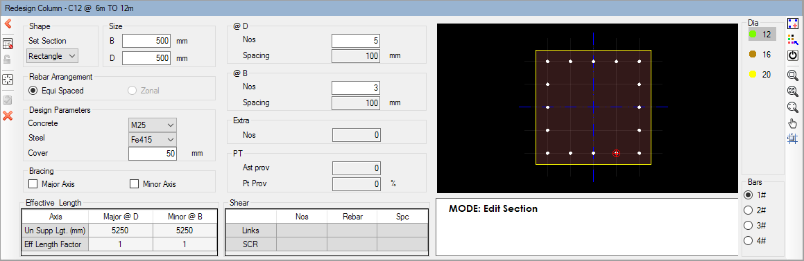
The Redsign Column dialog opens at the bottom of the program window.
select the Redesign Section tool

or
or
right-click on the column row and select Redesign Section from the pop-up menu
- In the Dia list, select 20 (mm) and then in the Bars list select 3#. This will place 20mm bars in groups of three in the section.
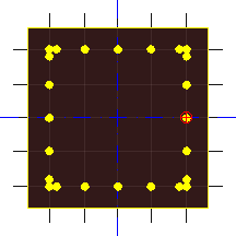
- Click on any of the corner bars in the cross section. The color-coded size of the grouped bars are added to each corner.
- Repeat steps 4c and 4d to add single (1#) 20mm bars along the faces.
-
Select the Redesign tool in the Redesign Grp dialog.
The column now passes design and detailing checks.
-
Select the Accept tool.

- Repeat step 4 to redesign the other failing column (C23).
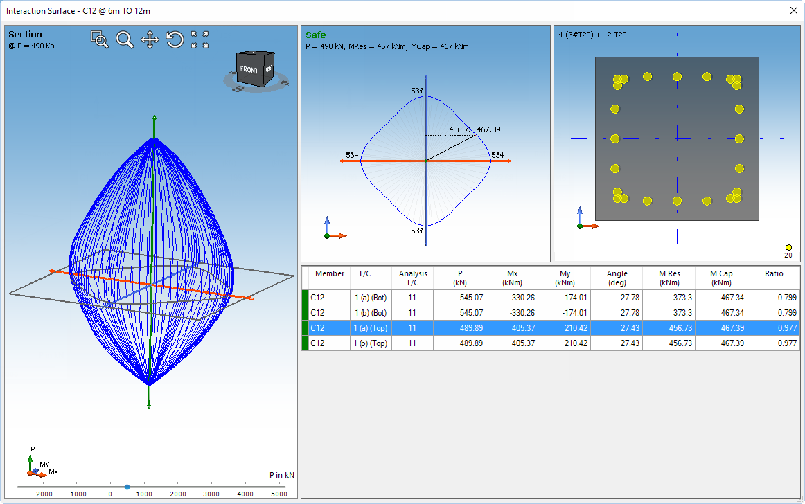
- Right-click on the second level column 12 (C12: 6m TO 12m) and select Interaction Surface from the pop-up menu. The Interaction Surface dialog opens.
-
Review the interaction surface:
Option Description To display the interaction at critical points for a load combination select that combination from the table To view the interaction at any point along the column height drag the slider to a specific load value To control the view of the interaction surface use the view controls at the top of the interaction surface view window - Click the X in top-right to close the Interaction Surface window.