AD.2007-03.1.6 IBC 2006
The static equivalent method for performing dynamic analysis as per the IBC 2006 code has been implemented. This follows the principals and methods as in the IBC 2000 and IBC 2003 codes previously implemented.
When the General | Load Page is selected, the right hand side of the screen will display the following if no load cases exist in the model.
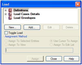
Definitions contains the options through which one creates the Define block of data required to create wind load cases, seismic load cases like IBC and UBC, moving load cases and time history load cases.
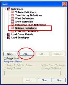
When the tree view is expanded, it will display thus:
In the dialog box that is displayed, select IBC 2006 from the drop-down list.
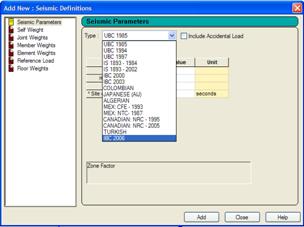
In this dialog box, the required data is entered into the parameters as described below.

There is an option to Include Accidental Load, if this is selected the analysis will include an additional accidental torsion component as described in section 12.8.4.2 of ASCE 7-05.
Refer to the Add New Seismic Definitions dialog and TR.31.2.14 IBC 2006/2009 Seismic Load Definition for details.
After specifying the values for the parameters, click on the Add button.
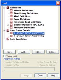
Note that the Load dialog box has been updated with the new command.

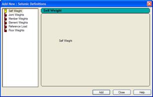
As described earlier, the second part of the process is to identify the structural weights that should be considered. These can be added once the defined parameters have been created by clicking on the Add button. The dialog box is updated to display the various weights that can be added thus:
Member Weights
Distributed and concentrated weights acting on member spans are specified through this option. After clicking the Member weight button, the Member weight dialog box appears, as shown below.
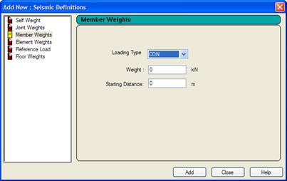
Select the Concentrated or Uniform load type from the Loading Type drop-down list. Enter the intensity of the distributed weight or magnitude of the concentrated weight as the case may be, along with the location of the load.
Element Weights
If the structural model consists of plate elements representing entities like floor slabs, the pressure loads on those slabs can be considered for weights calculation for lateral load generation per UBC/IBC/other codes. This is done with the help of the Element Weights option. Its parameters include the magnitude of the uniform pressure, and the elements they are applied on. Since it is a weight, it is a quantity without a sign.
Reference Load
Reference Load cases which are described in AD.2007-1001.1.12 of the STAAD.Pro 2007 Software Release Report can be referred to using this option. Loads which are specified under Reference Loads can be used as weights for IBC.
Floor Weights
In many situations, a user may decide not to include the structural slabs in his/her analytical model. Hence, the model may be solely the skeleton framing system consisting of the beams, columns and bracing members.
Under these circumstances, the loads which act on the slab can no longer be applied on the structure using the ELEMENT PRESSURE options. This is because there are no elements to represent the slab. So, an alternative is to apply the load using the FLOOR LOAD option. It is described in detail in TR.32.4 Area, One-way, and Floor Load Specifications.
Within a UBC/IBC/other codes definition, the FLOOR WEIGHT is the counterpart for the FLOOR LOAD just as MEMBER WEIGHT is the counterpart for a MEMBER LOAD, and an ELEMENT WEIGHT is the counterpart for an ELEMENT LOAD.
Once the seismic definition, including weights, has been specified, it should be included in a one or more primary load cases.
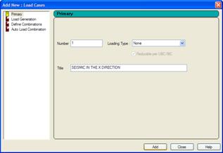
Select Load Cases Details and click on Add.

In the dialog box that is displayed, provide a Title, select the loading type as ‘seismic’ (although this is not strictly required, just useful for future reference) and click on Add.
More load cases can be added in this manner.
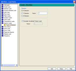
To add load items to our first load case, keep the expression 1: SEISMIC IN THE X DIRECTION highlighted and click on the Add button.
Enter the Factor, Direction, etc. and click on Add.
The Load dialog box will display the new load item.

We can continue adding other load items to this load case in a similar fashion.
For more information on other UBC and IBC load definitions, see TR.31.2 Definitions for Static Force Procedures for Seismic Analysis. To find more information about including the seismic loads in a primary load case, see TR.32.12 Generation of Loads.