D1.B.2.3 Design Procedure
Cross-Section Checks
The first check that is carried out is a verification whether the member properties satisfy certain basic requirements. If the member fails these checks, the remainder of the checks are not performed.
The cross section checks are the following:

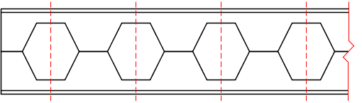
Castellated beam nomenclature
-
Web Post Width ( e ) should be at least 3.0 inches
-
Tee Depth ( dT-top and dT-bot ) should be greater than the thickness of flange plus one inch.
-
Angle θ should be between 45 and 70 degrees.
-
In order for the program to determine the number of holes which are admissible for the beam, the parameters SOPEN and EOPEN need to be assigned. In the figure above, there is a term shown as S. This value is part of the section tables supplied with STAAD.Pro, so it retrieves that value from there. It then computes the number of holes, and the remainder of the terms shown in the above diagram.
-
SOPEN and EOPEN (see the parameter table shown earlier) have to be at least 1.5e + b, with e and b as shown in the earlier figure. If you inputs a value less than these minima, the minimum values are used.
References
- Design of Welded Structures, Omer W. Blodget, published by The James Lincoln Arc Welding Foundation, pages 4.7-8 and 4.7-9
- AISC 9th edition manual – Allowable stress design
- ASCE Journal of Structural Engineering 124:10, October 1998, "Castellated Beam Web Buckling in Shear," R.G. Redwood and S. Demirdjian
Checking the member for adequacy in carrying the applied loading
This consists of five different checks:
-
Global Bending
-
Vierendeel Bending
-
Horizontal Shear
-
Vertical Shear
-
Web Post Buckling
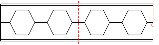
| Design For |
Section Considered in the Design (shown with the vertical dotted lines) |
|---|---|
| Vierendeel Bending |
|
|
Global Bending Vertical Shear Horizontal Shear Web Post Buckling |
|
-
Global Bending:
Global bending check is done at the web post section. This is the region of the member where the full cross section is active, without interference of the holes.
The actual bending stress is computed at the middle of the web post location and is obtained by dividing the moment by the section modulus of the full section.
For computing the allowable bending stress, the compactness of the section is first determined in accordance with Table B5.1 in the Chapter B of the AISC 9th edition specifications. The rules applicable to I-shaped sections are used for this. Following this, the allowable bending stress is computed per chapter F of the same.
The ratio is computed by dividing the actual stress by the allowable stress.
-
Vierendeel Bending:
This is checked at the middle of the hole locations. The effective cross section at these locations is a Tee. The overall moment (Mz) at the span point corresponding to the middle of the hole is converted to an axial force and a moment on the Tee.
The actual stress is computed at the top and bottom of each Tee section.
wherefa = M / ( deffect × At ) - At
= - area of the Tee section
wherefb = V × e × a / ( 2×S ) - a
= - the area factor. For the top Tee section, a = Area of Top Tee / ( Area of Top Tee + Area of Bottom Tee )
Allowable Stresses for vierendeel bending:
-
Axial Stress: The allowable axial stress is computed as per the Chapter E of the AISC specifications. The unsupported length for column buckling is equal to e.
-
Bending Stress: The allowable bending stress is computed for the top and bottom Tee section as per the Chapter F of the AISC manual.
The axial stress plus bending stress is computed at the top and bottom of each tee section. If it is compressive then it is checked against equations H1-1 and H1-2 of Chapter H of the AISC manual. If it is tensile then it is checked against equation H2-1
-
Horizontal Shear
Allowable Shear stress is computed as 0.4 Fy.
Actual Stress: Please refer to pages 4.7-8 and 4.7-9 of reference #1.
-
Vertical Shear
Allowable Shear stress is computed as 0.4 Fy.
The actual shear stress is computed at the middle of the web post location.
-
Web Post buckling
Refer to pages 1202-1207 of reference #3.