D1.J.2.6 Simple Joints: Capacity Checks
A typical joint and the terms involved with the joint checks are given below:
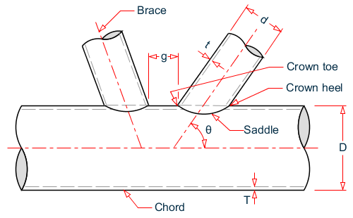
Simple joint diagram
Definitions
- θ = Brace included rage
- g = Gap between braces
- t = Brace wall thickness at intersection
- T = Chord wall thickness at intersection
- d = Brace outside diameter
- D = Chord outside diameter
| β = d/D |
| γ = D/(2T) |
| τ = t/T |
Joint Validity
The validity range of the joints that are identified will be checked as per Cl. 4.3.1 of the code. The conditions to be checked for each joint are as given below:
| 0.2 ≤ β ≤ 1.0 |
| 10 ≤ γ ≤ 50 |
| 30° ≤ θ ≤ 90° |
- Fy = 90 ksi (500 MPa)
- g/D > -0.6 (for K joints)
If any of these conditions are not satisfied for the joint under consideration, the programissues a warning message corresponding to the invalid parameter(s). The program will, however, perform the joint checks as the code allows for the design of such joints with modified values of yield strength. You can use the FYLD parameter to reset the yield strength.
Joint Capacity
The capacity of the joint, both the axial capacity and the moment capacity is
The allowable capacity for brace axial load, Pa, is evaluated as:
The allowable capacity for brace bending moment, Ma, is evaluated as:
Where:
- Fy = the yield stress of the chord member at the joint (or 0.8 of the tensile stress, if less)
- FSJ = the factor of safety parameter (1.6 by default)
- Qu and Qf are the strength factor and the Chord factor that are to be determined based on the joint type. The strength factor, Qu, is to be determined as given in Section 4.3.3 of the code (ref. Table. 4.3-1 of the API code).
- Pc = axial load
C1, C2, and C3 are factors determined by the following table:
| Joint Type | C1 | C2 | C3 | |
|---|---|---|---|---|
| K joints under brace axial loading | 0.2 | 0.2 | 0.3 | |
| T/Y joints under brace axial loading | 0.3 | 0 | 0.8 | |
| X joints under brace axial loading | β ≤ 0.9 | 0.2 | 0 | 0.5 |
| β = 1.0 | -0.2 | 0 | 0.4 | |
| All joints under brace moment loading | 0.2 | 0 | 0.4 | |
For joints that are a mixture of K, X, or Y joints, the capacity of the joint is evaluated as a weighted average of the capacities of each joint.
In case the joint is subjected to combined axial load and bending moments (in-plane and/or out-of-plane), the program performs the following interaction check as given by Cl 4.3.6 of the code: