D5.D.5.5 Clause 6.3.2.3(2) – Modification factor, f, for LTB checks
The UK NA specifies the use of eqn. 6.58 of BS EN 1993-1-1:2005 to evaluate the modification factor, f, for the LTB reduction factor χLT. To evaluate the modification factor BS EN 1993-1-1:2005 uses a correction factor kc given by Table 6.6 in the code.
The UK-NA however, specifies that the correction factor, kc, is to be obtained as below:
Kc = 1 / √C1, where C1 is to be obtained from the NCCI documents given in section 4.2 of this document. The NCCI document SN003a-EN-EU specifies the values of C1 to be used in table 3.1 as shown below. This proposed implementation will allow for the reduction factor based on the UK-NA.

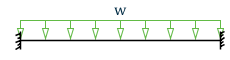
| Loading and support conditions | Bending moment diagram | C1 | C2 |
|---|---|---|---|
 |
 |
1.127 | 0.454 |
|

|
2.578 | 1.554 |

|

|
1.348 | 0.630 |

|

|
1.683 | 1.645 |
These values are for an end restraint factor of k=1 (i.e., CMN 1.0). Hence for all other values of CMN (i.e., 0.7 or 0.5) this implementation will use the values of C1 from DD ENV 1993-1-1:1992 Annex F.
The program will use a default value of 1.0 for kc. However the user can also input a custom value of kc by setting the design parameter KC to the desired value. The user can also get the program to calculate the value of kc automatically by setting the value of the KC parameter in the design input to 0. This will cause the program to evaluate a value of C1 corresponding to the end conditions and the Bending moment of the member and in turn calculate kc as given in the NA. To evaluate C1, the program will use the NCCI documents mentioned in section 4.2 of this document.