T.3 Specifying Supports
The slab is fixed-supported along the entire length of two adjacent sides. However, when modeled as plate elements, the supports can be specified only at the nodes along those edges, and not at any point between the nodes.
Tip: The finer
the mesh (i.e., the larger the number of elements), then the more supported
nodes you would be able to model. For this tutorial, the 2 meter mesh is used
as a simple demonstration.
The STAAD input file commands generated are:
SUPPORTS
1 2 4 5 7 10 FIXED-
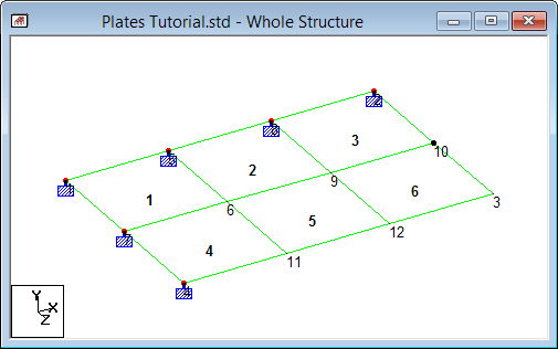
Press <Shift+N> to turn on the display of the
Node Numbers.
This will assist in the identification of the nodes used as supports.
-
On the
Geometry ribbon tab, select the
Nodes Cursor tool in the
Selection group.

-
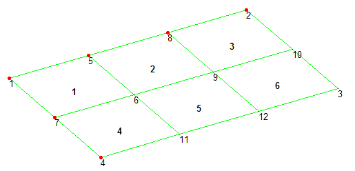
While pressing the <Ctrl> key, select the nodes on two
adjacent edges of the plate group:
These nodes are fixed supports in the model.
For example, in the following figure these nodes are:- 1
- 7
- 4
- 5
- 8
- 2
-
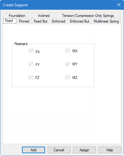
On the
Specification ribbon tab, select the
Fixed tool in the
Supports group.
The Create Support dialog opens with the Fixed tab selected.
- Click Assign.