To start the slab design
-
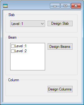
In the top-right dialog, select Level :1 from the drop-down list and then click Design Slab.
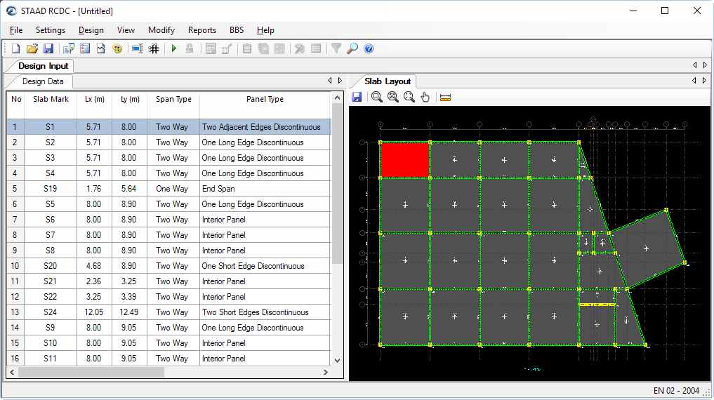
RCDC opens and the New Project dialog opens.
-
Enter the project data:

- Type Tutorial in the Project field.
- (Optional) Type Client and Engineer name. This information is used as the header for all reports. It will be automatically imported from the STAAD.Pro input file Job Information block if available.
- Select EN 02 - 2004 from the Design Code drop-down list. This tutorial uses the Eurocode. However, you can select any available code. Just note that some design settings and features may vary based on the code selection made here.
-
Either:
The Design Settings dialog opens.
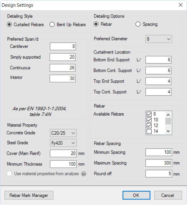
- In the Available Rebar list, clear the check mark by 25 (mm). This tutorial will limit the rebar size.
- Click OK.
-
Either:
The Crack Width Settings dialog opens.
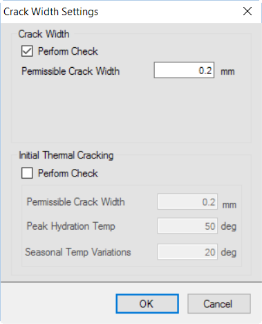
- Select the Perform Check option in the Crack Width group.
- Click OK.

