M. Polygonal Plate with Holes
Select the Polygonal Plate with Hole prototype under the model type Surfaces/Plates. Drag the item into the right-side window and release the button. The Define Meshing Region dialog box will appear as shown below.
The Polygonal prototype allows us to mesh a polygonal surface, with or without different kinds of holes inside the boundary, into small triangular plate elements.

Boundary
The Boundary tab as shown above in the Define Mesh Region dialog box provides us an option to specify the location of Corners, Number of Divisions of each side and Bias of each side's division for the Boundary to mesh the surface.
X, Y, Z are the coordinates of the various corners of the surfaces. The sides will be defined as joining the various corners. Div. option is to define the divisions of various sides of the polygonal surface to be considered for generating the surface meshing. The Bias option helps the user to create divisions having unequal spacings among them.
On the top of the right side of this dialog box there are two icons namely, Add New Row
 and Delete Row
 . Clicking on the first icon will add a new row enabling us to specify the coordinates of the corner of the polygonal surface. Clicking on the second icon will enable us to delete an existing row.
Holes
After creating the boundary, the user can start introducing the holes in the plate. In STAAD, we may create circular, elliptical as well as polygonal holes.
When we click on the HOLES option, two icons appear as shown below namely, Add New Hole
and Delete All Holes
.
| Setting | Description |
|---|---|
|
Add New Hole |
This icon allows us to add new holes to the surface. |
|
Delete All Holes |
This icon allows us to remove all the existing holes from the surface. Once a new hole is added, the name of the that hole appears under HOLES in a tree view. A new icon |
 titled
 Hole
To create a hole within the boundary, click this option. This is the default name of the hole. When we click on Hole, a table will be displayed on the right side of the dialog box, where we can define the geometry of the hole. Specify what kind of hole we want to create from among the three available options namely Polygon, Circle and Ellipse, in the Region Type, as shown in the next figure. For each hole, one tab will be created automatically in the Define Meshing Region dialog box to allow us to specify different parameters for that hole.

The creation and editing of the region types are explained below.
| Setting | Description |
|---|---|
| Polygon | This option is used to define polygonal holes. The geometry of the polygonal holes is generated in the same way as the geometry of the polygonal. Please refer to the description under polygonal surfaces for details on defining the geometry of polygonal holes. 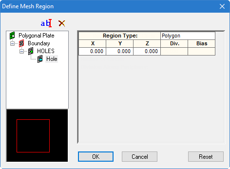
|
| Circle | This option is used to define circular holes. The parameters for defining the geometry of circular holes are described below: 
|
| Origin | We have to specify the X, Y, and Z coordinates in its proper places to define the position of the center of the circular hole. |
| Radius of circle | The value in this box will define the radius of the circular hole. |
| Division Along Periphery | The value in this box defines the number of divisions to be done along the circumference of the circular hole. This information will be considered in mesh generation of the surface |
| Ellipse | This option is used to generate ellipsoidal holes. The parameters to define the geometry of ellipsoidal holes are as follows:
|
| Origin | We have to specify the X, Y, and Z coordinates in its proper places to define the position of the center of the ellipsoidal holes. |
| Major Axis Radius, Minor Axis Radius | The values in these boxes will define the major axis and the minor axis of the ellipsoidal holes. |
| Division of each Quadrant | The values specified in this box specifies the number of divisions of each quadrant. This information will be used for the mesh generation of the surface. |
Once all the parameters have been specified, clicking on OK to carry out the mesh generation operation of the surface. Clicking on Cancel will cancel the mesh generation operation. Clicking on Reset will reset the parameters provided at the beginning.