V.Wind On Closed Structure 1
Evaluate the equivalent joint loads for a closed structure subjected to wind loads.
Details
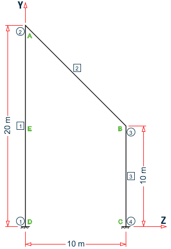
A structure lying in YZ plane is composed of three members and is subjected to wind load from (+X) direction (i.e., out-of-plane). Those three members, along with the ground surface, form a closed panel. The wind load incident on that panel is converted to equivalent joint loads incident on the nodes by the program.
The exposure factor, e, for the structure is 0.85.
Validation
Determine CG of the Wind Area
Naming the nodal points A, B, C, and D, divide the area into two sub-areas: a rectangle and a triangle. The division is taken at the mid-point of member 1, which is at the same Y ordinate as node 3 (point B).
Area of the triangle ABE = 1/2 × base × height = 1/2 ×(10m) ×(10m) = 50 m2
CG of triangle ABE: ,
Area of rectangle BCDE = 10 m × 10 m = 100 m2
CG of rectangle BCDE: ,
CG of total area ABCD: ,
The CG is labeled point P.
The influence area of each joint is then take as the midpoint of the connecting members to this CG. Label the mid-points of each member E, Q, and J. The point at support level between nodes 1 and 2 is labeled K.

Equivalent Joint Load on Node 2 (A)
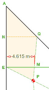
The influence area for node 2 is the shape formed by points A, Q, P, and E. Notice that this area can be decomposed into a trapezoid and two triangles. Also notice that this area has two different wind pressures, above and below y = 10m (which coincides with line EB). Label a point on line AE with the same Y coordinate as Q as N.
Determine the Z coordinate of where line EB intersects line PQ and label this point M.
slope of PQ = (15 - 7.77)/(5 - 4.44) = 13.0
z = 4.44 + (10 - 7.77)/13 = 4.615 m
The sub-areas of AQPE:
AEMP = 0.5×(10 - 7.77)×4.615 = 5.13 m2
ANQME = 0.5×(5+4.615)×5 = 24.04 m2
AANQ = 0.5×5×5 = 12.5 m2
The equivalent joint load, F, is calculated as Influence area, A, × avg. wind pressure, p × exposure factor, e
F = 0.85×[2×(5.13) + 3×(24.04 + 12.5)] = 101.90 kN
Equivalent Joint Load on Node 3 (B)
The influence area for node 3 is the shape formed by points B, J, P and Q. Label a point on line BJ with the same Y coordinate as P as point V.

The sub-areas of BJPQ:
ABMQ = 0.5×(10 - 4.615)×5 = 13.46 m2
ABVPM = 0.5×[(10 - 4.615) + (10 - 4.44)]×(10 - 7.77) = 12.2 m2
AVJP = 0.5×(10 - 4.44)×(7.77 - 5) = 7.72 m2
The equivalent joint load,
F = 0.85×[2×(12.2 + 7.72) + 3×(13.46)] = 67.85 kN
Equivalent Joint Load on Node 4 (C)
The influence area for node 4 is the shape formed by points C, K, P, and J. The change in pressure magnitude is at the same Y coordinate as point J. Label the point on line ED with this same Y coordinate as point R. Determine the Z coordinate of where line RJ intersects line PK and label this point W.
slope of PK = (7.77)/(5 - 4.44) = 14.0
z = 4.44 + (7.77 - 5)/14 = 4.643 m

The sub-areas of CKPJ:
AJWP = 0.5×(7.77 - 5)×(10 - 4.643) = 7.44 m2
ABVPM = 0.5×[(10 - 4.643) + 5]×5 = 25.89 m2
The equivalent joint load,
F = 0.85×[1.5×(25.89) + 2×(7.44)] = 45.66 kN
Equivalent Joint Load on Node 1 (D)
The influence area for node 1 is the shape formed by points D, E, P, and K. Label a point on line DE with the same Y coordinate as P as point L.

The sub-areas of DEPK:
ALEP = 0.5×(10 - 7.77)×4.44 = 4.94 m2
ARLPW = 0.5×[4.44 + 4.643]×(7.77 - 5) = 12.62 m2
ADRWK = 0.5×[4.643 + 5]×5 = 24.11 m2
The equivalent joint load,
F = 0.85×[1.5×(24.11) + 2×(4.94 + 12.62)] = 60.59 kN
STAAD.Pro Input File
The file C:\Users\Public\Public Documents\STAAD.Pro CONNECT Edition\Samples\ Verification Models\06 Loading\Wind Load\Wind On Closed Structure 1.STD is typically installed with the program.
STAAD SPACE
START JOB INFORMATION
ENGINEER DATE 30-Aug-18
END JOB INFORMATION
*******************************************************************************
* This problem is created to verify the calculations of equivalent -
* joint load on the joints of a closed structure subjected to wind load
*******************************************************************************
UNIT METER KN
JOINT COORDINATES
1 0 0 0; 2 0 20 0; 3 0 10 10; 4 0 0 10;
MEMBER INCIDENCES
1 1 2; 2 2 3; 3 3 4;
DEFINE MATERIAL START
ISOTROPIC CONCRETE
E 2.17185e+07
POISSON 0.17
DENSITY 23.5616
ALPHA 1e-05
DAMP 0.05
TYPE CONCRETE
STRENGTH FCU 27579
END DEFINE MATERIAL
MEMBER PROPERTY AMERICAN
1 TO 3 PRIS YD 0.4 ZD 0.4
CONSTANTS
MATERIAL CONCRETE ALL
SUPPORTS
1 4 FIXED
DEFINE WIND LOAD
TYPE 1 WIND 1
INT 1.5 2 3 HEIG  5  10  20
EXP 0.85 JOINT 1 TO 4
LOAD 1 LOADTYPE Wind  TITLE LOAD CASE 1
WIND LOAD X 1 TYPE 1 YR 0 20
PERFORM ANALYSIS PRINT LOAD DATA
FINISH
STAAD.Pro Output
   LOADING     1  LOADTYPE WIND  TITLE LOAD CASE 1
   -----------
   JOINT LOAD - UNIT KN   METE
   JOINT   FORCE-X   FORCE-Y     FORCE-Z     MOM-X     MOM-Y     MOM-Z
       1     60.59      0.00        0.00      0.00      0.00      0.00
       2    101.89      0.00        0.00      0.00      0.00      0.00
       3     68.11      0.00        0.00      0.00      0.00      0.00
       4     45.66      0.00        0.00      0.00      0.00      0.00
   ************ END OF DATA FROM INTERNAL STORAGE ************