V. IS 1893 2016 Torsion Irregularity
Verify part 1 of the torsional irregularity check per the IS 1893 2016 Part 1 specifications.
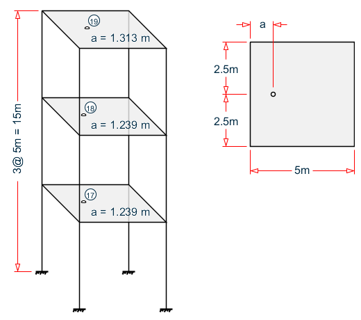
Details
A three story building is modelled with floor diaphragms defined at each floor level.
A 1 kip (4.4482 kN) load is applied to each diaphragm in both the global X and Z directions. In STAAD.Pro, this is modelled using an analytical node in each diaphragm. This is used to obtain the displacements in the nodes of the diaphragm.
Validation
As per Cl. 7.8.2, the design eccentricity, edi, is computed as the a constant times the dynamic eccentricity plus or minus the accidental eccentricity:
where| = | ||
| = |
Also, to perform a torsion irregularity check unit load should be applied at edi considering design eccentricity. Hence, in addition to unit load F = 1 kip (4.45 kN), a moment M = F × (lever arm) is also applied at the center of mass.
The displacements induced because of the applied loads on the control nodes for the nodes situated on the extremities of each diaphragm is taken from the STAAD.Pro output for each lateral direction.
X direction
By inspection, the center of rigidity (as reported by STAAD.Pro) and the center of mass are located at the same point at each floor. Therefore, esi = 0.
| Diaphragm | Control Node | esi (m) (C.M. - C.R.) | Dynamic Eccentricity (1.5esi) | Accidental Eccentricity (0.05bi) | Design Eccentricity (e di = 1.5esi+0.05bi) |
Fx Applied at C.M. | My Applied at CM
(Fx×(edi-esi) |
|---|---|---|---|---|---|---|---|
| 1 | 17 | 0 | 0 | 0.25 | 0.25 | 4.45 | 1.11 |
| 2 | 18 | 0 | 0 | 0.25 | 0.25 | 4.45 | 1.11 |
| 3 | 19 | 0 | 0 | 0.25 | 0.25 | 4.45 | 1.11 |
| Diaphragm | Control Node | esi (m) (C.M. - C.R.) | Dynamic Eccentricity (1.0esi) | Accidental Eccentricity (-0.05bi) | Design Eccentricity (e di = 1.0esi-0.05bi) |
Fx Applied at C.M. | My Applied at CM
(Fx×(edi-esi) |
|---|---|---|---|---|---|---|---|
| 1 | 17 | 0 | 0 | -0.25 | -0.25 | 4.45 | -1.11 |
| 2 | 18 | 0 | 0 | -0.25 | -0.25 | 4.45 | -1.11 |
| 3 | 19 | 0 | 0 | -0.25 | -0.25 | 4.45 | -1.11 |
The displacements induced because of the applied loads centers of mass for the nodes situated on the extremities of each diaphragm are taken from the STAAD.Pro output for each lateral direction.
| Diaphragm | Control Node | Primary LC Number | Diaphragm Extremities | Displacements (mm) | Δmax/Δavg | Status | |||
|---|---|---|---|---|---|---|---|---|---|
| Extreme Node 1 | Extreme Node 2 | Δx Extreme Node 1 | Δx Extreme Node 2 | Δx Average | |||||
| 1 | 17 | 1 | 2 or 3 | 6 or 7 | 0.466 | 0.498 | 0.482 | 1.033 | PASS |
| 2 | 18 | 2 | 9 or 10 | 11 or 12 | 2.399 | 2.487 | 2.443 | 1.018 | PASS |
| 3 | 19 | 3 | 13 or 14 | 15 or 16 | 6.016 | 6.164 | 6.090 | 1.012 | PASS |
| Diaphragm | Control Node | Primary LC Number | Diaphragm Extremities | Displacements (mm) | Δmax/Δavg | Status | |||
|---|---|---|---|---|---|---|---|---|---|
| Extreme Node 1 | Extreme Node 2 | Δx Extreme Node 1 | Δx Extreme Node 2 | Δx Average | |||||
| 1 | 17 | 4 | 2 or 3 | 6 or 7 | 0.498 | 0.466 | 0.482 | 1.033 | PASS |
| 2 | 18 | 5 | 9 or 10 | 11 or 12 | 2.487 | 2.399 | 2.443 | 1.018 | PASS |
| 3 | 19 | 6 | 13 or 14 | 15 or 16 | 6.164 | 6.016 | 6.090 | 1.012 | PASS |
Z direction checks
| Diaphragm | Control Node | C.R. (from output file) | esi (m) (C.M. - C.R.) | Dynamic Eccentricity (1.5esi) | Accidental Eccentricity (0.05bi) | Design Eccentricity (e di = 1.5esi+0.05bi) |
Fx Applied at C.M. | My Applied at CM
(Fx×(edi-esi) |
|---|---|---|---|---|---|---|---|---|
| 1 | 17 | 0.247 | 1.239 - 0.247 = 0.992 | 1.488 | 0.25 | 1.738 | 4.45 | 3.32 |
| 2 | 18 | 0.319 | 1.239 - 0.319 = 0.92 | 1.380 | 0.25 | 1.630 | 4.45 | 3.16 |
| 3 | 19 | 0.372 | 1.313 - 0.372 = 0.941 | 1.412 | 0.25 | 1.662 | 4.45 | 3.20 |
| Diaphragm | Control Node | C.R. (from output file) | esi (m) (C.M. - C.R.) | Dynamic Eccentricity (1.0esi) | Accidental Eccentricity (-0.05bi) | Design Eccentricity (e di = 1.0esi-0.05bi) |
Fx Applied at C.M. | My Applied at CM
(Fx×(edi-esi) |
|---|---|---|---|---|---|---|---|---|
| 1 | 17 | 0.247 | 1.239 - 0.247 = 0.992 | 0.992 | -0.25 | 0.742 | 4.45 | -1.11 |
| 2 | 18 | 0.319 | 1.239 - 0.319 = 0.92 | 0.920 | -0.25 | 0.670 | 4.45 | -1.11 |
| 3 | 19 | 0.372 | 1.313 - 0.372 = 0.941 | 0.941 | -0.25 | 0.691 | 4.45 | -1.11 |
| Diaphragm | Control Node | Primary LC Number | Diaphragm Extremities | Displacements (mm) | Δmax/Δavg | Status | |||
|---|---|---|---|---|---|---|---|---|---|
| Extreme Node 1 | Extreme Node 2 | Δz Extreme Node 1 | Δz Extreme Node 2 | Δz average | |||||
| 1 | 17 | 7 | 2 or 6 | 3 or 7 | 0.238 | 0.27 | 0.254 | 1.063 | PASS |
| 2 | 18 | 8 | 9 or 11 | 10 or 12 | 0.935 | 1.009 | 0.972 | 1.038 | PASS |
| 3 | 19 | 9 | 13 or 15 | 14 or 16 | 1.916 | 2.046 | 1.981 | 1.033 | PASS |
| Diaphragm | Control Node | Primary LC Number | Diaphragm Extremities | Displacements (mm) | Δmax/Δavg | Status | |||
|---|---|---|---|---|---|---|---|---|---|
| Extreme Node 1 | Extreme Node 2 | Δz Extreme Node 1 | Δz Extreme Node 2 | Δz average | |||||
| 1 | 17 | 10 | 2 or 6 | 3 or 7 | 0.232 | 0.392 | 0.312 | 1.256 | WARNING |
| 2 | 18 | 11 | 9 or 11 | 10 or 12 | 0.913 | 1.325 | 1.119 | 1.184 | PASS |
| 3 | 19 | 12 | 13 or 15 | 14 or 16 | 1.873 | 2.578 | 2.226 | 1.158 | PASS |
Results
| Result Type | Floor | Reference | STAAD.Pro | Difference | Comments |
|---|---|---|---|---|---|
| X Direction; Case 1 | 1 | PASS (1.033) | PASS (1.0333) | negligible | |
| 2 | PASS (1.018) | PASS (1.0180) | negligible | ||
| 3 | PASS (1.012) | PASS (1.0122) | negligible | ||
| X Direction; Case 2 | 1 | PASS (1.033) | PASS (1.0333) | negligible | |
| 2 | PASS (1.018) | PASS (1.0180) | negligible | ||
| 3 | PASS (1.012) | PASS (1.0122) | negligible | ||
| Z Direction; Case 1 | 1 | PASS (1.063) | PASS (1.0622) | negligible | |
| 2 | PASS (1.038) | PASS (1.0381) | negligible | ||
| 3 | PASS (1.033) | PASS (1.0329) | negligible | ||
| Z Direction; Case 2 | 1 | WARNING (1.256) | WARNING (1.2562) | negligible | |
| 2 | PASS (1.184) | PASS (1.1841) | negligible | ||
| 3 | PASS (1.158) | PASS (1.1584) | negligible |
STAAD.Pro Input File
The file C:\Users\Public\Public Documents\STAAD.Pro CONNECT Edition\Samples\ Verification Models\06 Loading\IS 1893\IS 1893 2016 Torsion Irregularity.STD is typically installed with the program.
STAAD SPACE
START JOB INFORMATION
ENGINEER DATE 05-Mar-19
END JOB INFORMATION
INPUT WIDTH 79
UNIT METER KN
JOINT COORDINATES
1 0 0 0; 2 0 5 0; 3 5 5 0; 4 5 0 0; 5 0 0 5; 6 0 5 5; 7 5 5 5; 8 5 0 5;
9 0 10 0; 10 5 10 0; 11 0 10 5; 12 5 10 5; 13 0 15 0; 14 5 15 0; 15 0 15 5;
16 5 15 5; 17 1.239 5 2.5; 18 1.239 10 2.5; 19 1.313 15 2.5
MEMBER INCIDENCES
1 1 2; 2 2 3; 3 3 4; 4 2 6; 5 3 7; 6 5 6; 7 6 7; 8 7 8; 9 2 9; 10 3 10;
11 6 11; 12 7 12; 13 9 10; 14 9 11; 15 10 12; 16 11 12; 17 9 13; 18 10 14;
19 11 15; 20 12 16; 21 13 14; 22 13 15; 23 14 16; 24 15 16;
DEFINE MATERIAL START
ISOTROPIC CONCRETE
E 2.17185e+07
POISSON 0.17
DENSITY 23.5616
ALPHA 1e-05
DAMP 0.05
TYPE CONCRETE
STRENGTH FCU 27579
END DEFINE MATERIAL
MEMBER PROPERTY AMERICAN
2 3 5 7 8 10 12 13 15 16 18 20 21 23 24 PRIS YD 0.35 ZD 0.25
MEMBER PROPERTY AMERICAN
1 4 6 9 11 14 17 19 22 PRIS YD 0.5 ZD 0.65
CONSTANTS
MATERIAL CONCRETE ALL
SUPPORTS
1 4 5 8 FIXED
*MEMBER CRACKED CODE IS1893 2016
*1 3 6 8 TO 12 17 TO 20 REDUCTION RIY 0.7 RIZ 0.7
*2 4 5 7 13 TO 16 21 TO 24 REDUCTION RIY 0.35 RIZ 0.35
MEMBER CRACKED
1 3 6 8 TO 12 17 TO 20 REDUCTION RIY 0.7 RIZ 0.7
2 4 5 7 13 TO 16 21 TO 24 REDUCTION RIY 0.35 RIZ 0.35
DEFINE REFERENCE LOADS
LOAD R1 LOADTYPE Mass  TITLE REF LOAD CASE 1
SELFWEIGHT X 1
SELFWEIGHT Y 1
SELFWEIGHT Z 1
END DEFINE REFERENCE LOADS
FLOOR DIAPHRAGM
DIA 1 TYPE RIG HEI 5
DIA 2 TYPE RIG HEI 10
DIA 3 TYPE RIG HEI 15
CHECK IRREGULARITIES CODE IS1893 2016
DEFINE IS1893 2016 LOAD
ZONE 0.36 RF 5 I 1.2 SS 1 ST 5 DM 0.05
LOAD 1 LOADTYPE None  TITLE Diaphragm 1 Case 1 X Dir
JOINT LOAD
17 FX 4.4482 MY 1.11205
LOAD 2 LOADTYPE None  TITLE Diaphragm 2 Case 1 X Dir
JOINT LOAD
18 FX 4.4482 MY 1.11205
LOAD 3 LOADTYPE None  TITLE Diaphragm 3 Case 1 X Dir
JOINT LOAD
19 FX 4.4482 MY 1.11205
LOAD 4 LOADTYPE None  TITLE Diaphragm 1 Case 2 X Dir
JOINT LOAD
17 FX 4.4482 MY -1.11205
LOAD 5 LOADTYPE None  TITLE Diaphragm 2 Case 2 X Dir
JOINT LOAD
18 FX 4.4482 MY -1.11205
LOAD 6 LOADTYPE None  TITLE Diaphragm 3 Case 2 X Dir
JOINT LOAD
19 FX 4.4482 MY -1.11205
LOAD 7 LOADTYPE None  TITLE Diaphragm 1 Case 1 Z Dir
JOINT LOAD
17 FZ 4.4482 MY 3.3183572
LOAD 8 LOADTYPE None  TITLE Diaphragm 2 Case 1 Z Dir
JOINT LOAD
18 FZ 4.4482 MY 3.158222
LOAD 9 LOADTYPE None  TITLE Diaphragm 3 Case 1 Z Dir
JOINT LOAD
19 FZ 4.4482 MY 3.2049281
LOAD 10 LOADTYPE None  TITLE Diaphragm 1 Case 2 Z Dir
JOINT LOAD
17 FZ 4.4482 MY -1.11205
LOAD 11 LOADTYPE None  TITLE Diaphragm 2 Case 2 Z Dir
JOINT LOAD
18 FZ 4.4482 MY -1.11205
LOAD 12 LOADTYPE None  TITLE Diaphragm 3 Case 2 Z Dir
JOINT LOAD
19 FZ 4.4482 MY -1.11205
PERFORM ANALYSIS
PRINT ANALYSIS RESULTS
PRINT DIA CR
FINISH
STAAD.Pro Output
 -IRREGULARITY CHECKS
                    STAAD.PRO IRREGULARITIES CHECK - (  IS1893-2016  )   v1.2
                    *********************************************************
                         Including Amendment no. 2 November 2020
                    *********************************************************
 --TORSION IRREGULARITY CHECKS
 Torsion Irregularity Check
 Ref: Table 5 (i)    - Ratio Limit(s): Lower-1.20 Upper-1.40
 ---------------------------------------------------------------------
 edi : Design Eccentricity
 esi : Static Eccentricity
 bi  : Floor/Diaphragm plan dimension perpendicular to force direction
 For Details Refer Clause 7.8 IS1893:2016-Part-1
 ---------------------------------------------------------------------
 Using edi = 1.5esi + 0.05bi
 ---------------------------
 Displacement of extreme points of diaphragm(dia.) in X dir.
 ------------------------------------------------------------------------
  Dia.  Node Max. Disp.  Node Min. Disp. Avg. Disp. Max./Avg.  Status
                 (mm)             (mm)      (mm)      Disp.
 ------------------------------------------------------------------------
    1      7    0.4984      2    0.4662    0.4823    1.0333     PASS
    2     12    2.4871      9    2.3990    2.4430    1.0180     PASS
    3     16    6.1637     13    6.0157    6.0897    1.0122     PASS
 Using edi = esi - 0.05bi
 ------------------------
 Displacement of extreme points of diaphragm(dia.) in X dir.
 ------------------------------------------------------------------------
  Dia.  Node Max. Disp.  Node Min. Disp. Avg. Disp. Max./Avg.  Status
                 (mm)             (mm)      (mm)      Disp.
 ------------------------------------------------------------------------
    1      2    0.4984      7    0.4662    0.4823    1.0333     PASS
    2      9    2.4871     12    2.3990    2.4430    1.0180     PASS
    3     13    6.1637     16    6.0157    6.0897    1.0122     PASS
 Using edi = 1.5esi + 0.05bi
 ---------------------------
 Displacement of extreme points of diaphragm(dia.) in Z dir.
 ------------------------------------------------------------------------
  Dia.  Node Max. Disp.  Node Min. Disp. Avg. Disp. Max./Avg.  Status
                 (mm)             (mm)      (mm)      Disp.
 ------------------------------------------------------------------------
    1      3    0.2699      2    0.2383    0.2541    1.0622     PASS
    2     10    1.0087      9    0.9347    0.9717    1.0381     PASS
    3     14    2.0463     13    1.9160    1.9812    1.0329     PASS
 Using edi = esi - 0.05bi
 ------------------------
 Displacement of extreme points of diaphragm(dia.) in Z dir.
 ------------------------------------------------------------------------
  Dia.  Node Max. Disp.  Node Min. Disp. Avg. Disp. Max./Avg.  Status
                 (mm)             (mm)      (mm)      Disp.
 ------------------------------------------------------------------------
    1      3    0.3916      2    0.2319    0.3118    1.2562   WARNING*
    2     10    1.3253      9    0.9131    1.1192    1.1841     PASS
    3     14    2.5782     13    1.8732    2.2257    1.1584     PASS
   *** WARNING: The floor is irregular.  Please ensure conformance
    with Cl. 7.1, Table 5, Sl No. (i) sec-i.a or sec-i.b.
 --GEOMETRY IRREGULARITY CHECKS
 Re-Entrant Corner Check.
 (Ref: Table 5 (ii)   - Ratio Limit: 0.15 )
 ------------------------------------------
   ***NOTE: No Irregular Re-Entrant Nodes found in the diaphragm.
   ***NOTE: No Irregular Re-Entrant Nodes found in the diaphragm.
   ***NOTE: No Irregular Re-Entrant Nodes found in the diaphragm.
 --MASS IRREGULARITY CHECKS
 Mass Irregularity Check
 Ref: Table 6 (ii)   - Ratio Limit: 1.50
 ---------------------------------------
 Dia.   Level     Mass       Above      Below     Ratio  Ratio  Status
        ( m)      ( kN)      ( kN)      ( kN)     Above  Below
 ---------------------------------------------------------------------
    1     5.000    166.404    166.404    Base      1.000   N/A     OK
    2    10.000    166.404    117.808    166.404   1.412  1.000    OK
    3    15.000    117.808    Top        166.404    N/A   0.708    OK
   ***NOTE: Linear dynamic analysis needs to carried out for Irregular
   Modes of Oscillation check.
   ***NOTE: Static Seismic Loads for relevant code needs to be defined
   with Zone 4 and 5 for Irregular Modes of Oscillation  check.