AD.2005.1.6 Stretch Members
This new facility allows one to increase the length of a member in various ways. The benefit it offers is that a member may be extended even if one does not readily know the coordinates of its ends joints in its stretched condition, something a user may appreciate in the case of members whose axis lie at an inclination to the global planes.
Description
Select the member which is to be extended. In the Geometry menu at the top of the screen, the option called Stretch Selected Member(s) becomes active.

Click on it and the following dialog box will appear.

The various options of the dialog box are explained below.
- Select member(s)
- Multiple members can be selected simultaneously for stretching. However, whether they will get stretched or not depends upon the type of method used in stretching as described later. If you wish to remove one or more members from the list, uncheck the corresponding boxes.
 Uncheck those members which you do not wish to stretch.
The methods available for stretching are:
- To a point
- Specify the coordinates in current length units of the point to which one of the ends of the member are to be moved. The point must lie on the axis of the member being stretched, or else, the stretching will not be performed. The program automatically determines which of the two ends of the member is to be moved. So, this method involves
- determining if the point lies on the axis of the member(s) being stretched.
- determining which end to move for the member(s) which satisfy criteria (i)
- replacing the corresponding nodal coordinates with those of the desired point.
- Through a distance
- In this method, the user has to merely specify the distance by which the start or end node must be stretched.
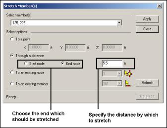 Choose the end which should be stretched. Specify the distance by which to stretch.
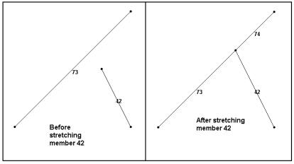
In this method, all members selected for this operation will see the change in length. The next diagram illustrates this. If this causes member to cross each other, the user must create the intersection point using the Geometry – Intersect Selected Members tool as the program does not automatically create it in the Stretch operation.
 Before stretching the top node (left). After stretching the top nodes (right).
 - To an existing node
- This is very similar to the To a point method described earlier. The only difference is that instead of explicitly specifying the coordinates of the desired point, that point is already available for identification through its node number.
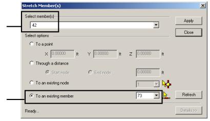
- To an existing member
- If 2 members are oriented in such a manner that the local X-axis of one of those members can potentially intersect a second member within the span of that member, this method may be used to stretch the first member to meet the second member. In the next figure, member 42 may be stretched so it meets member 73. The second member will be automatically split up at the intersection point into two segments.
The dialog box settings required to achieve this are as follows:
Notes
In the To an existing node method, a graphical tool is available for selecting the node from the drawing as shown in the next figure.
In the To an existing member method, a graphical tool is available for selecting the member from the drawing as shown in the next figure.
 In the To an existing node method, use this tool graphically select an existing node from the model.
 In the To an existing member method, use this tool graphically select an existing node from the model.
The Details button may be switched on to view the internal details of the stretch operation.
