Unsupported Effective Length and Effective Length Coefficient
The unsupported effective length and effective length coefficient are the calculation parameters needed to check the stability of members.
The direction of the strong axis and the weak axis of the principal inertial axis should be considered respectively. For complex spatial structures, it is very difficult to select the effective length and effective length coefficient of members. For the convenience of users, the function of automatically calculating these coefficients is set up in the program. Of course, users can also input these coefficients themselves. When these coefficients are automatically calculated by the program, they are calculated according to the following principles.
For the principal inertial axis (the strong axis is the local Z-axis and the weak axis is the local Y-axis), the effective length of the member can be expressed as follows:
where| = | ||
| = | For P-Delta solution sets, the effective length coefficients are always taken as 1.0. | |
| = |
In the Chinese Steel Design workflow, the structure is divided into element and member system, and analyzed and calculated by finite element method. In some cases, it is possible that only one direction (such as the main axis direction) is supported at the node, while the other direction (such as the weak axis direction) is not supported. In this case, and are not equal, and they are not necessarily the distance between two nodes. For example, for the element [1] in the figure below, there is a horizontal member (unit 3) supporting at node 2 in the direction of the main axis, while there is no support at node 2 in the direction of the secondary axis. Therefore, the unsupported length of the member [1] in the direction of the principal axis and the unsupported length in the secondary axis direction.
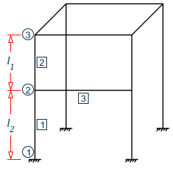
In some cases, you may add several nodes between members, and these nodes are only used for calculation, not nodes in the geometric sense. For example, as shown in the figure below, if a node (node 2) is added in the middle of a vertical column, then the unsupported length of element [1] and element [2] should be instead of or during stability check.

For this kind of component, there is no problem in the structural analysis. But for the component design, it must be considered.
According to the provisions of GB 50017-2017, the members requiring stability analysis and calculation can be divided into three categories (the following are divided into three categories A, B and C).
Truss Chords and Single Web Members
For this kind of member, the provisions in table 7.4.1-1 in the specification can be adopted and .
For example, the Chord in the plane of the truss, ,and web in the plane of the truss .
For this kind of component, you need to input the calculated length.
Uniform Section Column of Single or Multi Story Frame
For frame columns, the ratios K1 and K2 of the sum of the linear stiffness of the beams intersecting the upper and lower ends of the column and the sum of the linear stiffness of the column are required, and then the following equation is solved
- For non-sway frame columns:
- For sway frame columns:
In the Chinese Steel Design workflow, you can input the length coefficient and unsupported length of members, and it can also be calculated automatically by the program. In this case, it is necessary to specify the supporting condition of the component (whether the two principal axes belong to the component with or without lateral displacement respectively).
For the calculation of unsupported length, there are several cases as follows:
- The longitudinal inclined strut is shown in the figure below.

In this case, the program will judge whether the constraint effect of the bar on the column should be considered according to the size of α angle. If α ≤ 60 ° (this can be specified), the program considers that the strut has constraint on the corresponding main axis direction of the column, and the linear stiffness of the strut is added to the total linear stiffness of the beam in proportion to calculate the value of K1 or K2.
- Horizontal non principal inertial axis direction strut, as shown in the
following figure:

In this case, the program will also automatically judge whether the constraint of the bar to the main axis of the column should be considered according to the size of the β angle.
If β is less than 60 °, which you can be specify, the strut is considered as a constraint on the strong axis direction of the column, and the linear stiffness of the strut is added to the total linear stiffness of the beam in the strong axis direction of the column.
- The column extension angle is used to allow the engineer to set the maximum
angle if the column is not on the same line but has an included angle when
calculating the unsupported length of the column. Note that the angle should not
exceed 30 degrees.
Finally, the unsupported length ( and ) and the effective length coefficient of the column in the strong axis and weak axis direction () are calculated automatically
Rigid Fixed Stepped Column at the Lower End of Frame of Single Story Workshop
This kind of column is mostly used in the concrete column of heavy workshop. Generally, there are single and double order columns. Because in the steel structure, this kind of stepped column is not very useful. Therefore, for this kind of component, the user should input it manually after calculation according to 8.3.2 and 8.3.3 of the specification.
For single angle steel, when the length coefficient is calculated automatically, you can select to calculate by parallel limb (Y-Z axis) or strong weak axis (U-V axis) in the Design Parameters dialog box.