T.2 Creating the model using the command file
As an alternatively to the procedures described in the proceeding tutorial, you can also create the same STAAD input file using the STAAD.Pro Editor.
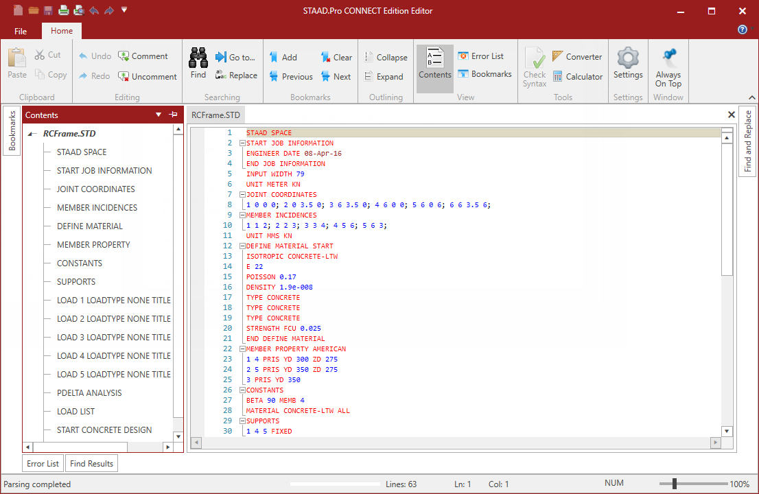
To start a new STAAD input file using the STAAD.Pro Editor, follow the procedure described in Creating a new structure. Then select the Command File tool in the Edit group on the Utilities ribbon tab. The STAAD.Pro Editor window opens with the basic commands for your model entered.
For this tutorial, delete all the command lines displayed in the editor window and type the lines shown below. While not necessary, this will allow you to learn more about the required and optional command lines for an input file.
STAAD commands are not case sensitive (i.e., they may be typed in upper or lower case letters). By convention, this and most input files use all caps, though.
For most all commands and keywords, the first three letters of a keyword are all that are needed. The rest of the letters of the word are not required, but are useful to present a user-friendly command language in mostly plain English for later reference. By convention, the required letters in a command or keyword are underlined here ("PLANE" = "PLA" = "plane" = "pla").
STAAD SPACE RC FRAMED STRUCTUREEvery input has to start with the word STAAD. The word SPACE signifies that the structure is a space frame structure (3-D) and the geometry is defined through X, Y and Z coordinates.
JOINT COORDINATES
1 0 0 0 ; 2 0 3.5 0 ; 3 6 3.5 0
4 6 0 0 ; 5 6 0 6 ; 6 6 3.5 6Joint number followed by X, Y and Z coordinates are provided above. Semicolon signs (;) are used as line separators. That enables you to provide multiple sets of data on one line.
UNIT MMS
KN
MEMBER PROPERTY AMERICAN
1 4 PRIS YD 300 ZD 275
2 5 PRIS YD 350 ZD 275
3 PRIS YD 350Member properties have been defined above using the PRISMATIC attribute for which YD (depth) and ZD (width) values are provided in MM unit. When YD and ZD are provided together, STAAD considers the section to be rectangular. When YD alone is specified, the section is considered to be circular. Details are available in Technical Reference of STAAD Commands.
CONSTANTS
E 22 MEMB 1 TO 5Material constant E (modulus of elasticity) is specified as 22KN/sq.mm following the command CONSTANTS.
UNIT METER KN
CONSTANTS
DENSITY 25.0 ALL
POISSON 0.17 ALLLength unit is changed from MMS to METER to facilitate the input of Density. Next, the Poisson's Ratio is specified.
BETA 90 MEMB 4In the absence of any explicit instructions, STAAD will orient the beams and columns of the structure in a pre-defined way (see General Engineering Theory for details.) In order to orient member 4 so that its longer edges (sides parallel to local Y axis) are parallel to the global Z axis, you must apply a beta angle of 90 degrees.
UNIT METER KG
LOAD 1 DEAD LOADForce units are changed from KN to KG to facilitate the input of loads. Load case 1 is initiated along with an accompanying title.
SELFWEIGHT Y -1One of the components of load case 1 is the selfweight of the structure acting in the global Y direction with a factor of -1.0. Since global Y is vertically upward, the factor of -1.0 indicates that this load will act downwards.
MEMBER LOAD
2 5 UNI
GY -400Load 1 contains member loads also. GY indicates that the load is in the global Y direction. The word UNI stands for uniformly distributed load. Loads are applied on members 2 and 5.
MEMBER LOAD
2 5 UNI
GY -600Load 2 also contains member loads. GY indicates that the load is in the global Y direction. The word UNI stands for uniformly distributed load. Loads are applied on members 2 and 5.
MEMBER LOAD
1 UNI
GX 300
4 UNI
GX 500Load 3 also contains member loads. GX indicates that the load is in the global X direction. The word UNI stands for uniformly distributed load. Loads are applied on members 1 and 4.
REPEAT LOAD
1 1.2 2 1.5Load case 4 illustrates the technique employed to instruct STAAD to create a load case which consists of data to be assembled from other load cases specified earlier. This repeat load case instructs the program to analyze the structure for loads from cases 1 and 2 acting simultaneously. The load data values from load case 1 are multiplied by a factor of 1.2, and the resulting values are utilized in load case 4. Similarly, the load data values from load case 2 are multiplied by a factor of 1.5, and the resulting values too are utilized in load case 4.
REPEAT LOAD
1 1.1 3 1.3This repeat load case instructs the program to analyze the structure for loads from cases 1 and 3 acting simultaneously.
PDELTA ANALYSISThe PDELTA ANALYSIS command is an instruction to the program to execute a second-order analysis and account for P-delta effects.
LOAD LIST 4 5The above LOAD LIST command is a means of stating that all further calculations should be based on the results of load cases 4 and 5 only. The intent here is to restrict concrete design calculations to that for load cases 4 and 5 only.
START CONCRETE DESIGN
CODE ACI
UNIT MMS
NEWTON
CLT 25 ALL
CLB 30 ALL
CLS 25 ALL
FC 25 ALL
FYMAIN 415 ALL
TRACK 1 ALLThe first line is the command that initiates the concrete design operation. The values for the concrete design parameters are defined in the above commands. Design is performed per the ACI Code. The length units are changed from METER to MMS to facilitate the input of the design parameters. Similarly, force units are changed from KG to NEWTON. The TRACK value dictates the extent of design related information which should be produced by the program in the output. The parameters specified include CLT (Clear cover for top surface), CLB (Clear cover for bottom surface), CLS (Clear cover for sides), FC(Strength of concrete), and FYMAIN (Ultimate strength of steel). These parameters are described in D1.F.3 Design Parameters.