D5.B.6 Design Parameters
Design parameters communicate specific design decisions to the program. They are set to default values to begin with and may be altered to suite the particular structure.
Depending on the model being designed, the user may have to change some or all of the parameter default values. Some parameters are unit dependent and when altered, the new setting must be compatible with the active unit specification.
The following table lists all the relevant EC3 parameters together with description and default values.
| Parameter Name | Default Value | Description |
|---|---|---|
| CODE | Undefined |
You must specify EC3 or EUROPE. Design code to follow. See TR.48.1 Parameter Specifications. |
| BEAM | 3 |
Parameter to control the number of sections to checked along the length of a beam:
Refer to Note 2 below. |
| CAN | 0 |
Member will be considered as a cantilever type member for deflection checks. 0 indicates that member will not be treated as a cantilever member 1 indicates that the member will be treated as a cantilever member |
| CMM | 1.0 |
Indicates type of loading on member. Valid values range from 1 to 6. Refer to Table 7B.3 for more information on its use. |
| CMN | 1.0 |
Indicates the level of End-Restraint.
|
| DMAX | 100.0 cm | Maximum allowable depth for the member. |
| DMIN | 0 | Minimum required depth for the member. |
| DFF | None (Mandatory for deflection check) | Deflection limit |
| DJ1 | Start Joint of member | Joint No. denoting starting point for calculation of "Deflection Length". |
| DJ2 | End Joint of member | Joint No. denoting end point for calculation of "Deflection Length". |
| FU | Ultimate tensile strength of steel | |
| GB1 | 1.1 | Partial safety factor used in buckling checks for compression members |
| GM0 | 1.1 | Corresponds to the Γm0 factor in DD ENV 1993-1-1:1992 |
| GM1 | 1.1 | Corresponds to the Γm1 factor in DD ENV 1993-1-1:1992 |
| GM2 | 1.1 | Corresponds to the Γm2 factor in DD ENV 1993-1-1:1992 |
| KY | 1.0 | K factor in local y axis. |
| KZ | 1.0 | K factor in local z axis. |
| LEG | 0.0 |
Connection type Refer to Note 1 below. |
| LVV | Maximum of Lyy and Lzz (Lyy is a term used by BS5950) | Buckling length for angle about its principle axis |
| LY | Member Length | Compression length in local y axis, Slenderness ratio = (KY)*(LY)/(Ryy) |
| LZ | Member Length | Compression length in local z axis, Slenderness ratio = (KZ)*(LZ)/(Rzz) |
| PLG | 0 |
(Polish NA only) Perform additional checks per Cl. 6.3.3
Refer to D5.D.8.7 Clause 6.3.3(5) – Interaction factors kyy, kyz, kzy, and kzz |
| PY | Yield Strength | The yield strength default value is set based on the default value of the "SGR" parameter. |
| NSF | 1.0 | Net tension factor for tension capacity calculation. |
| RATIO | 1 | Permissible ratio of loading to capacity. |
| SBLT | 0.0 |
Indicates if the section is rolled or built-up.
|
| SGR | 0.0 |
Steel grade as per table 3.1 in EC3.
|
| TRACK | 0 |
Controls the level of detail of output.
See note 3 below. |
| UNF | 1.0 | Unsupported buckling length as a factor of the beam length |
| UNL | Member Length | Unrestraint length of member used in calculating the lateral-torsional resistance moment of the member. |
| ZIV | 0.8 | Specifies a reduction factor for vectoral effects to be used in axial tension checks [Cl 5.5.3(2)] |
Notes
-
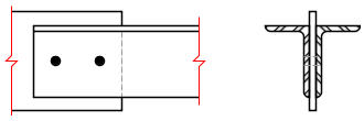
LEG – (Ref: Table 25 BS5950)
The slenderness of single and double angle, channel and tee sections are specified in BS 5950 table 25 depending on the connection provided at the end of the member (Refer to section 5B.5(A).2). To define the appropriate connection, a LEG parameter should be assigned to the member.
The following table indicates the value of the LEG parameter required to match the BS5950 connection definition:
Table 2. LEG Parameter values Clause Bolt Configuration Leg LEG Parameter 4.7.10.2
Single Angle
(a) - 2 bolts short leg
1 long leg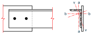
3 (b) - 1 bolts short leg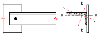
0 long leg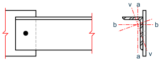
2 4.7.10.3 Double Angles (a) - 2 bolts short leg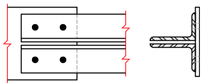
3 long leg
7 (b) - 1 bolts short leg
2 long leg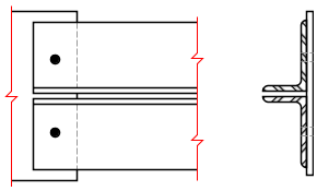
6 (c) - 2 bolts long leg 1 short leg
5 (d) - 1 bolts long leg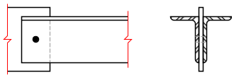
0 short leg
4 4.7.10.4 Channels (a) - 2 or more rows of bolts 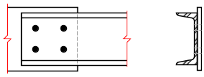
1 (b) - 1 row of bolts 
0 4.7.10.5 Tee Sections (a) - 2 or more rows of bolts 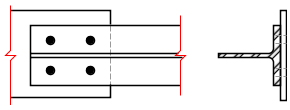
1 (b) - 1 row of bolts 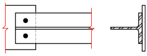
0 For single angles, the slenderness is calculated for the geometric axes, a-a and b-b as well as the weak v-v axis. The effective lengths of the geometric axes are defined as:
La = KY * KY Lb = KZ * LZ The slenderness calculated for the v-v axis is then used to calculate the compression strength pc for the weaker principal axis (z-z for ST angles or y-y for RA specified angles). The maximum slenderness of the a-a and b-b axes is used to calculate the compression strength pc for the stronger principal axis.
Alternatively for single angles where the connection is not known or Table 25 is not appropriate, by setting the LEG parameter to 10, slenderness is calculated for the two principal axes y-y and z-z only. The LVV parameter is not used.
For double angles, the LVV parameter is available to comply with note 5 in table 25. In addition, if using double angles from user tables, ( G.6.3 User-Provided Steel Table ) an eleventh value, rvv, should be supplied at the end of the ten existing values corresponding to the radius of gyration of the single angle making up the pair.
-
BEAM
Ensure that this parameter is set to either 1 or 2 while performing code checking for members susceptible to Lateral - Torsional Buckling.
Table 3. Values for the CMM Parameter CMM Value Loading and Support Conditions 1 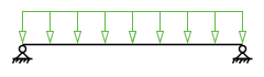
2 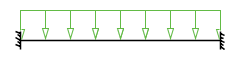
3 
4 
5 
6 
-
Checking beam deflection
With the TRACK parameter set to 4, the members included in a CHECK CODE command will be checked for the local axis deflection rather than for the stress capacity using the current LOAD LIST.
If both stress capacity and deflection checks are required, then 2 parameter blocks with code checks are required, one with a TRACK 4 command and one with a TRACK 0, 1, or 2, thus:
LOAD LIST 1 TO 10
PARAMETER 1
CODE EN 1993
TRACK 2 ALL
CHECK CODE MEMBER 1
***************************
LOAD LIST 100 TO 110
PARAMETER 2
TRACK 4 ALL
DFF 300 MEMB 1
DJ1 1 MEMB 1
DJ2 4 MEMB 1
CODE MEMB 1