T.3 Creating the Plates - Method 4
To create the plates using the Mesh Generation facility, use the following steps.
This method uses the same drawing grid from Method 1. Refer to " T.3 Setup the Grid."
The STAAD.Pro GUI contains a facility for generating a mesh of elements from a boundary (or superelement) defined by a set of corner nodes. The boundary must form a closed surface and must lie within a plane, though that plane can be inclined to any of the global planes.
You define the boundary by selecting the corner nodes. If these nodes do not exist, they must be created before they can be selected.
- Create the nodes:
- In the Snap Node/Plate dialog, click Close.
- Use the Plates Cursor and select this plate.
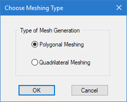
- To start a quadrilateral mesh of the existing plate element:
- Complete the meshing parameters:
-
Re-number the plate elements:
-
On the
Plate Tools ribbon tab, select the
Renumber Plates tool in the
Model group.

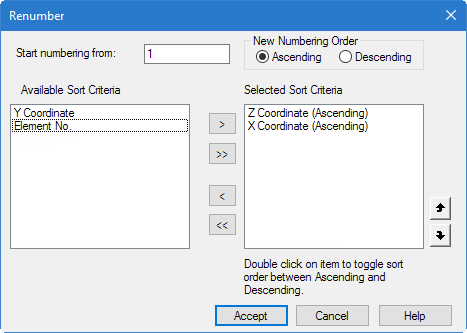
A warning message opens. - Click Yes. The Renumber dialog opens.
- Double-click Z Coordinate in the Available Sort Criteria list.
- Double-click X Coordinate in the Available Sort Criteria list. The Z coordinate entry should appear above the X coordinate entry in the Selected Sort Criteria list.
- Click Accept.
-
On the
Plate Tools ribbon tab, select the
Renumber Plates tool in the
Model group.


As an alternative in step 1, you can press and hold <Ctrl> to
create only disconnected nodes. Then, when you can use the
tool in the
Plate group on the
Geometry ribbon tab to generate the plates from
those nodes, rather than re-meshing an existing plate. You then use the plate
bound selection cursor
 to select these
corner nodes to define a meshed boundary.
to select these
corner nodes to define a meshed boundary.