To perform the beam design
- Either: An exceptions dialog opens indicating that two beams have failed the design checks.
- Click OK.
- Either: The Failure Diagnostics tab opens. The table indicates that many beams are failing due detailing checks.
-
Evaluate some options for beam group 2:
- Select any of the beam segments in G2 in the Design Output table. The beam segments in this group are marked with a red tag to indicate the group failed one or more checks.
- Either: The Redsign Grp dialog opens at the bottom of the program window.
- Type 3 in the Bar Layers at Top field.
-
Select the Redesign tool in the Redesign Grp dialog.
 The beam now passes design and crack width checks.
-
Select the Accept tool.

-
Repeat step 4 to redesign G7 with 3 layers of top bars as well.
Optionally, you can use the UnLock tool
 to unlock the current design and then change the initial settings to use larger reinforcement sizes.
-
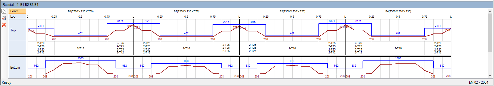
Review the detailing on the demand and capacity curve for a beam:
- Select beam group G1 and either: The Redtail dialog opens at the bottom of the program window.
- Click-and-drag your mouse cursor over the beam subdivisions starting at 0.75L of the first beam span in G1.
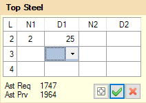
- Right-click and select detail from the pop-up menu. The Top Steel pop-up dialog opens.
- Delete the N1 value for layer 4 and then select the empty value for D1 for the same layer. This will remove the fourth layer of bars from the top steel in this segment, creating a new reinforcement detail for the selected segment.
-
Click OK.
 The section of the capacity curve for the top steel updates to reflect the detailing change.
-
Click Cancel.

- (Optional) Check for any resized beams during design by selecting . A report including any resized beams during design opens. For this example, none of the beams were resized.