P. Beam Combined Axial and Bending Stress table
Presents the combined bending stress results at key cross-section points along the member length for each load case.
All tab
This tab presents combined axial and bending stress at four corners of the member cross section at the specified number of intermediate sections. The Maximum Compressive and Maximum Tensile stresses are also listed. The result is given for all selected Load Cases.
The points on the cross-section where the stresses are reported are identified by the numbers 1, 2, 3, and 4. The locations of these points are identified in the following figure by section type.
 I shape |
 channel |
 double channel |
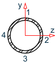 pipe |
 tube |
 T shape |
 single angle |
 double angle |
Max Stresses tab
This tab presents the Maximum Compressive and Maximum Tensile Stresses for all Members for all selected Load Cases. The stresses at all intermediate sections and at both ends are considered. The point of occurrence (position along length) of the Maximum stress is listed in the Length column. The corner of the beam at which the stress occurs is listed under the Corner column.
Profile Stress Points tab
The forces and stresses ( Combined Axial and Bending Stresses ) can be obtained at certain selected points on a cross section and can be added to the table. Type in the Dist value, local Y distance on the cross section (Stress Pt(Y)), and the local Z distance on the cross section (Stress Pt(Z)).