V. ASCE 7-16 Wind Load Generation on Tank
Verify the windward loads due to wind on a portion of a tank structure calculated per the ASCE 7-16 specification.
Details
The wind load is calculated for a tank structure using the direction procedure for MWFRS of enclosed buildings (ASCE 7-16, Chapter 27). The following assumptions and parameters apply:
- Category II building (Table 1.5-1)
- Basic wind speed = 108 mph
- Ground height above sea level = 520 ft
- Structure type of "chimney, tank, or similar structure"
- Exposure Category B
- Wind speed-up over hills or escarpments is considered: a two-dimension ridge of height, H = 300 ft. The distance upwind of crest, Lh = 650 ft and the distance from crest to the building, x = 750 ft
- Height of tank = 40 ft
- The least horizontal dimension (W or D), D = 25 ft
- Round axisymmetric horizontal cross-section
- Depth of protruding elements, D' = 0.5 ft
- Natural frequency of structure = 2 Hz (i.e., a "rigid" building per Cl. 26.2)
- Damping ratio = 0.01
Determine the wind loads acting on a vertical portion of the upper tank structure at a two-panel segment tangent to the YZ plane. For the purpose of this example, the contributions of the surrounding tank portions are ignored (i.e., only the portions of the wind area in this segment are calculated for brevity).

Wind load portion considered on tank structure

Loaded area plan and elevation
Validation
Directionality factor, Kd = 1.0 (Table 26.6-1)
Topographic factor, Kzt
For a 2D ridge, K1/(H/Lh) = 1.30, γ = 3, μ = 1.5 (Fig 26.8-1):
As Kzt is a function of height, it must be calculated at each elevation. Refer to the table below.
Ground elevation factor, (Table 26.9-1)
The velocity pressure exposure coefficients (Kz) are calculated per the formulae given in Table 26.10-1:
| (Table 26.10.1) |
| = | ||
| = |
See the table below for the values of Kz at discrete values of z.
Velocity pressure, qz
| qz = 0.00256×KzKztKdKeV2 | (Cl. 26.10-1) |
Mean roof height = height of the building = 40 ft. Refer to table below for calculation of qz at the mean roof height.
Gust effect factor, G
G is calculated per Cl. 26.11.4 for rigid structures:
| (Cl. 26.11.4) |
| = | ||
| = | ||
| = | ||
| = | ||
| = | ||
| = | ||
| = | ||
| = |
Force Coefficient, Cf
- h/D = 40/25 = 1.6, so must linearly interpolate between 1 and 7.
D'/D = 0.5/25 = 0.02
, so the type of surface is "rough"- The minimum value of corresponds to the maximum value of qz, which is taken from the tabulated values below (at height, z = 40 ft).
- The minimum value of
- Linearly interpolate between values:
| p = qz×G×Cf | (Eq. 29.4-1) |
| h (ft) | Kz | z/Lh | K3 | Kzt | qz (lb/ft2) |
p (lb/ft2) |
|---|---|---|---|---|---|---|
| 0 | 0.575 | 0 | 1 | 1.296 | 21.83 | 13.42 |
| 8 | 0.575 | 0.012 | 0.964 | 1.285 | 21.64 | 13.30 |
| 16 | 0.585 | 0.025 | 0.929 | 1.274 | 21.85 | 13.43 |
| 24 | 0.657 | 0.037 | 0.895 | 1.263 | 24.33 | 14.96 |
| 27 | 0.680 | 0.042 | 0.883 | 1.259 | 25.09 | 15.42 |
| 29.5 | 0.697 | 0.045 | 0.873 | 1.256 | 25.67 | 15.78 |
| 32 | 0.714 | 0.049 | 0.863 | 1.253 | 26.21 | 16.11 |
| 34.5 | 0.729 | 0.053 | 0.853 | 1.250 | 26.71 | 16.42 |
| 37 | 0.744 | 0.057 | 0.843 | 1.247 | 27.18 | 16.71 |
| 40 | 0.761 | 0.062 | 0.831 | 1.243 | 27.72 | 17.04 |
Load on Nodes 10 and 12

Tributary area for nodes 10 and 12
Wind pressure at half-way between this node and level above (29.5') = 15.78 lb/ft2.
F = (3.09 ft / 2) × (5 ft / 2) × 15.78 lb/ft2 (10)-3 = 0.060 kips
Load on Node 11
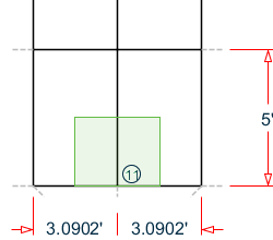
Tributary area for node 11
Wind pressure at half-way between this node and level above (29.5') = 15.78 lb/ft2.
F = (3.09 ft) × (5 ft / 2) × 15.78 lb/ft2 (10)-3 = 0.120 kips
Load on Nodes 102 and 104

Tributary area for nodes 102 and 104
Wind pressure at half-way between this node and level below (29.5') = 16.11 lb/ft2.
Wind pressure at half-way between this node and level above (34.5') = 16.42 lb/ft2.
F = (3.09 ft / 2) × (5 ft / 2) × (16.11 lb/ft2 + 16.42 lb/ft2) (10)-3 = 0.126 kips
Load on Node 103

Tributary area for node 103
Wind pressure at half-way between this node and level below (34.5') = 16.11 lb/ft2.
Wind pressure at half-way between this node and level above (29.5') = 16.42lb/ft2.
F = (3.09 ft) × (5 ft / 2) × (16.11 lb/ft2 + 16.42 lb/ft2) (10)-3 = 0.251 kips
Load on Nodes 30 and 32

Tributary area for nodes 30 and 32
Wind pressure at top of tributary area (37') = 16.71 lb/ft2.
F = (3.09 ft / 2) × (5 ft / 2) × 16.71 lb/ft2 (10)-3 = 0.065 kips
Load on Node 31
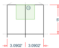
Tributary area for node 31
Wind pressure at top of tributary area (37') = 16.71 lb/ft2.
F = (3.09 ft) × (5 ft / 2) × 16.71 lb/ft2 (10)-3 = 0.129 kips
Results
| Result Type | Reference | STAAD.Pro | Difference | Comments |
|---|---|---|---|---|
| Node 10 | 0.060 | 0.06 | none | |
| Node 11 | 0.120 | 0.12 | none | |
| Node 12 | 0.060 | 0.06 | none | |
| Node 102 | 0.126 | 0.13 | negligible | |
| Node 103 | 0.251 | 0.25 | negligible | |
| Node 104 | 0.126 | 0.13 | negligible | |
| Node 30 | 0.065 | 0.06 | negligible | |
| Node 31 | 0.129 | 0.13 | negligible | |
| Node 32 | 0.065 | 0.06 | negligible |
STAAD.Pro Input
The file C:\Users\Public\Public Documents\STAAD.Pro CONNECT Edition\Samples\ Verification Models\06 Loading\Wind Load\ASCE 7-16 Wind Load Generation on Tank.STD is typically installed with the program.
STAAD SPACE
START JOB INFORMATION
ENGINEER DATE 16-Sep-20
END JOB INFORMATION
INPUT WIDTH 79
UNIT FEET KIP
JOINT COORDINATES
1 10 27 0; 2 9.51057 27 -3.09017; 3 8.09017 27 -5.87785; 4 5.87785 27 -8.09017;
5 3.09017 27 -9.51057; 6 6.12323e-16 27 -10; 7 -3.09017 27 -9.51057;
8 -5.87785 27 -8.09017; 9 -8.09017 27 -5.87785; 10 -9.51057 27 -3.09017;
11 -10 27 -1.22465e-15; 12 -9.51057 27 3.09017; 13 -8.09017 27 5.87785;
14 -5.87785 27 8.09017; 15 -3.09017 27 9.51057; 16 -1.83697e-15 27 10;
17 3.09017 27 9.51057; 18 5.87785 27 8.09017; 19 8.09017 27 5.87785;
20 9.51057 27 3.09017; 21 10 37 0; 22 9.51057 37 -3.09017;
23 8.09017 37 -5.87785; 24 5.87785 37 -8.09017; 25 3.09017 37 -9.51057;
26 6.12323e-16 37 -10; 27 -3.09017 37 -9.51057; 28 -5.87785 37 -8.09017;
29 -8.09017 37 -5.87785; 30 -9.51057 37 -3.09017; 31 -10 37 -1.22465e-15;
32 -9.51057 37 3.09017; 33 -8.09017 37 5.87785; 34 -5.87785 37 8.09017;
35 -3.09017 37 9.51057; 36 -1.83697e-15 37 10; 37 3.09017 37 9.51057;
38 5.87785 37 8.09017; 39 8.09017 37 5.87785; 40 9.51057 37 3.09017; 41 0 40 0;
42 5 24 0; 43 4.75528 24 -1.54508; 44 4.04508 24 -2.93893;
45 2.93893 24 -4.04508; 46 1.54508 24 -4.75528; 47 3.06162e-16 24 -5;
48 -1.54508 24 -4.75528; 49 -2.93893 24 -4.04508; 50 -4.04508 24 -2.93893;
51 -4.75528 24 -1.54508; 52 -5 24 -6.12323e-16; 53 -4.75528 24 1.54508;
54 -4.04508 24 2.93893; 55 -2.93893 24 4.04508; 56 -1.54508 24 4.75528;
57 -9.18485e-16 24 5; 58 1.54508 24 4.75528; 59 2.93893 24 4.04508;
60 4.04508 24 2.93893; 61 4.75528 24 1.54508; 62 0 25.5 0;
63 -2.93893 16 4.04508; 64 -2.93893 8 4.04508; 65 -2.93893 0 4.04508;
66 2.03368 24 4.56773; 67 2.03368 16 4.56773; 68 2.03368 8 4.56773;
69 2.03368 0 4.56773; 70 4.97261 24 0.522642; 71 4.97261 16 0.522642;
72 4.97261 8 0.522642; 73 4.97261 0 0.522642; 74 2.93893 16 -4.04508;
75 2.93893 8 -4.04508; 76 2.93893 0 -4.04508; 77 -2.03368 24 -4.56773;
78 -2.03368 16 -4.56773; 79 -2.03368 8 -4.56773; 80 -2.03368 0 -4.56773;
81 -4.97261 24 -0.522642; 82 -4.97261 16 -0.522642; 83 -4.97261 8 -0.522642;
84 -4.97261 0 -0.522642; 85 -8.09017 32 5.87785; 86 -5.87785 32 8.09017;
87 -3.09017 32 9.51057; 88 -1.83697e-15 32 10; 89 3.09017 32 9.51057;
90 5.87785 32 8.09017; 91 8.09017 32 5.87785; 92 9.51057 32 3.09017;
93 10 32 0; 94 9.51057 32 -3.09017; 95 8.09017 32 -5.87785;
96 5.87785 32 -8.09017; 97 3.09017 32 -9.51057; 98 6.12323e-16 32 -10;
99 -3.09017 32 -9.51057; 100 -5.87785 32 -8.09017; 101 -8.09017 32 -5.87785;
102 -9.51057 32 -3.09017; 103 -10 32 -1.22465e-15; 104 -9.51057 32 3.09017;
MEMBER INCIDENCES
1 1 2; 2 2 3; 3 3 4; 4 4 5; 5 5 6; 6 6 7; 7 7 8; 8 8 9; 9 9 10; 10 10 11;
11 11 12; 12 12 13; 13 13 14; 14 14 15; 15 15 16; 16 16 17; 17 17 18; 18 18 19;
19 19 20; 20 20 1; 21 21 22; 22 22 23; 23 23 24; 24 24 25; 25 25 26; 26 26 27;
27 27 28; 28 28 29; 29 29 30; 30 30 31; 31 31 32; 32 32 33; 33 33 34; 34 34 35;
35 35 36; 36 36 37; 37 37 38; 38 38 39; 39 39 40; 40 40 21; 41 1 93; 42 2 94;
43 3 95; 44 4 96; 45 5 97; 46 6 98; 47 7 99; 48 8 100; 49 9 101; 50 10 102;
51 11 103; 52 12 104; 53 13 85; 54 14 86; 55 15 87; 56 16 88; 57 17 89;
58 18 90; 59 19 91; 60 20 92; 61 41 34; 62 41 35; 63 41 36; 64 41 37; 65 41 38;
66 41 39; 67 41 40; 68 41 21; 69 41 22; 70 41 23; 71 41 24; 72 41 25; 73 41 26;
74 41 27; 75 41 28; 76 41 29; 77 41 30; 78 41 31; 79 41 32; 80 41 33; 81 42 43;
82 43 44; 83 44 45; 84 45 46; 85 46 47; 86 47 48; 87 48 49; 88 49 50; 89 50 51;
90 51 52; 91 52 53; 92 53 54; 93 54 55; 94 55 56; 95 56 57; 96 57 58; 97 58 59;
98 59 60; 99 60 61; 100 61 42; 101 14 55; 102 15 56; 103 16 57; 104 17 58;
105 18 59; 106 19 60; 107 20 61; 108 1 42; 109 2 43; 110 3 44; 111 4 45;
112 5 46; 113 6 47; 114 7 48; 115 8 49; 116 9 50; 117 10 51; 118 11 52;
119 12 53; 120 13 54; 121 62 55; 122 62 56; 123 62 57; 124 62 58; 125 62 59;
126 62 60; 127 62 61; 128 62 42; 129 62 43; 130 62 44; 131 62 45; 132 62 46;
133 62 47; 134 62 48; 135 62 49; 136 62 50; 137 62 51; 138 62 52; 139 62 53;
140 62 54; 141 55 63; 142 63 64; 143 64 65; 144 55 66; 145 63 67; 146 64 68;
147 66 67; 148 67 68; 149 68 69; 150 66 70; 151 67 71; 152 68 72; 153 70 71;
154 71 72; 155 72 73; 156 70 45; 157 71 74; 158 72 75; 159 45 74; 160 74 75;
161 75 76; 162 45 77; 163 74 78; 164 75 79; 165 77 78; 166 78 79; 167 79 80;
168 77 81; 169 78 82; 170 79 83; 171 81 82; 172 82 83; 173 83 84; 174 81 55;
175 82 63; 176 83 64; 257 85 33; 258 86 34; 259 85 86; 260 87 35; 261 86 87;
262 88 36; 263 87 88; 264 89 37; 265 88 89; 266 90 38; 267 89 90; 268 91 39;
269 90 91; 270 92 40; 271 91 92; 272 93 21; 273 92 93; 274 94 22; 275 93 94;
276 95 23; 277 94 95; 278 96 24; 279 95 96; 280 97 25; 281 96 97; 282 98 26;
283 97 98; 284 99 27; 285 98 99; 286 100 28; 287 99 100; 288 101 29;
289 100 101; 290 102 30; 291 101 102; 292 103 31; 293 102 103; 294 104 32;
295 103 104; 296 104 85;
DEFINE MATERIAL START
ISOTROPIC CONCRETE
E 453600
POISSON 0.17
DENSITY 0.14999
ALPHA 5.5e-06
DAMP 0.05
TYPE CONCRETE
STRENGTH FCU 576
END DEFINE MATERIAL
MEMBER PROPERTY
141 TO 143 147 TO 149 153 TO 155 159 TO 161 165 TO 167 171 TO 173 PRIS YD 2.5
145 146 151 152 157 158 163 164 169 170 175 176 PRIS YD 3 ZD 2
1 TO 140 144 150 156 162 168 174 257 TO 296 PRIS YD 1 ZD 1
CONSTANTS
MATERIAL CONCRETE ALL
SUPPORTS
65 69 73 76 80 84 FIXED
DEFINE WIND LOAD
TYPE 1 ASCE 7:2016
<! STAAD PRO GENERATED DATA DO NOT MODIFY !!!
ASCE-7-2016:PARAMS 108.000 MPH 520.000 FT 1 1 1 1 750.000 FT 650.000 FT -
300.000 FT 0 6 40.000 FT 25.000 FT 0.500 FT 2.000 0.010 0 0 0 0 0 0.761 -
1.243 1.000 1.000 0.981 0 0 0 0 0.866 0.710 1.000
!> END GENERATED DATA BLOCK
INT 0.0132004 0.0132004 0.0136356 0.0140333 0.0143996 0.0147394 0.0150565 -
0.0153537 0.0156335 0.0158978 0.0161483 0.0163864 0.0166132 0.0168298 -
0.017037 HEIG 0 15 16.9231 18.8461 20.7692 22.6923 24.6154 26.5385 28.4615 -
30.3846 32.3077 34.2308 36.1538 38.0769 40
EXP 1 JOINT 1 TO 84
LOAD 1 LOADTYPE Wind  TITLE WL
WIND LOAD X 1 TYPE 1 YR 27 37 ZR -5 5
PERFORM ANALYSIS PRINT LOAD DATA
FINISH
STAAD.Pro Output
   LOADING     1  LOADTYPE WIND  TITLE WL
   -----------
   JOINT LOAD - UNIT KIP  FEET
   JOINT   FORCE-X   FORCE-Y     FORCE-Z     MOM-X     MOM-Y     MOM-Z
      10      0.06      0.00        0.00      0.00      0.00      0.00
      11      0.12      0.00        0.00      0.00      0.00      0.00
      12      0.06      0.00        0.00      0.00      0.00      0.00
      30      0.06      0.00        0.00      0.00      0.00      0.00
      31      0.13      0.00        0.00      0.00      0.00      0.00
      32      0.06      0.00        0.00      0.00      0.00      0.00
     102      0.13      0.00        0.00      0.00      0.00      0.00
     103      0.25      0.00        0.00      0.00      0.00      0.00
     104      0.13      0.00        0.00      0.00      0.00      0.00