AD.2006.2.1 Generation of Transfer Force Report for Connection Design
STAAD.Pro can now calculate the "Transfer force" or "pass through force" that can be used for connection design. This feature is based on a paper on the subject by Dr. William. A. Thornton. Refer to the next figure which shows beams and bracing members connected to either side of the column.
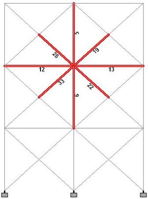
Transfer force is simply the maximum net horizontal force that gets transferred from the one side of the column to the other through the connection. So STAAD.Pro checks the forces in the members framing into each side of the column and finds out the resultant horizontal force for either side. Typically the resultant forces on the two sides would not be equal as some amount of force will be taken up by the column in shear. The greater of the two resultants is reported by STAAD.Pro as the transfer force. The option to determine transfer force automatically, will save engineers considerable time and effort as in most cases, they have to report the transfer forces in the design drawings. The transfer force feature only works for a beam column bracing system lying in a vertical plane.
Description
Go to the Post processing mode by selecting Mode | Postprocessing or by clicking on the Postprocessing tab above the graphics window. Select all the members that frame into any connection as shown in the previous figure. Then select .
A dialog box titled Transfer Force for Selected Members comes up as shown in the next figure. The Loads box displays the load cases that has been considered to calculate the transfer force. By default all load cases are considered but one can exclude a few of them by simply clicking on the load case within the Loads box. The boxes Left Beams and Right Beams list all the members on the respective sides of the column along with their incidences. The boxes Left TF and Right TF shows the resultant horizontal force from either side. Max TF reports the transfer force.

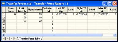
Click on the Insert to Table button and a table will be generated containing all the transfer force information as shown in the next figure.
The transfer force information can also be included as part of a report by selecting or by selecting the Report Setup tool  which will open the Report Setup dialog box as shown in the next figure.

By default, the Transfer Force Report appears in the selected list of items within the dialog box. A report with the transfer force data can then be generated as shown next.
