EX. To design the box section
-
「仕様」リボンタブで、「ビームのプロファイル」グループのツールの順に選択します。

「ユーザー定義テーブル」がない場合は、1つ作成するように指示されます。
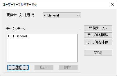
「ユーザーテーブルマネージャ」ダイアログが開きます。 - 「新規テーブル」をクリックします。 「新規ユーザーテーブル」ダイアログが開きます。
-
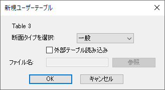
Specify the new external table:
- 「断面タイプを選択」リストから「一般」を選択します。
- 「外部テーブル読み込み」オプションをオンにします。
- 「参照」をクリックします。
- Navigate to and select the file Bsection.upt exported from Section Wizard and then click OK.
- In the User Table Manager dialog, click Close.
-
次のどちらかを行います。
「STAAD解析と設計」ダイアログが開きます。
解析(およびある場合は設計)中に出力ファイルが生成されます。このファイルには、選択された入力データ項目、結果、およびエラーメッセージが含まれます。印刷オプションは出力ファイルに追加情報を含めるために使用します。
- 「終了」をクリックします。
-
Select Chinese Steel Design in the
Workflows panel.

-
On the Chinese Steel Design ribbon tab, select the
General Section tool in the Settings group.

The General Section dialog opens. -
Select the table row for BOX1 and then
enter the section values as follows:
Field Value Flange Width between 2 Webs 0.972 m Thickness of Flange (TF) 0.024 m Height of Web (BW) 1.552 m Thickness of Web (TW) 0.014 m 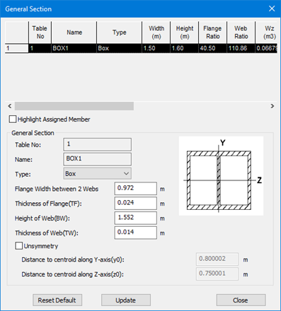
- Click Close.
-
On the Chinese Steel Design ribbon tab,
select the Design tool in the
Design group.

The Chinese Steel Design dialog opens. - Click Design. The design progress is displayed.
- Click Done.