D5.B.5.2 Design of Axially Loaded Members
The design of members subject to tension loads alone are performed as per Cl 5.4.3 of the code. The tension capacity is calculated based on yield strength, material factor Γm and cross-sectional area of the member with possible reduction due to bolt holes. When bolt holes need to be considered in the capacity calculations the value used for Γm is 1.2 and the yield strength is replaced with the ultimate tensile strength of the material. The tension capacity is then taken as the smaller of the full section capacity and the reduced section capacity as stated above.
The design of members subject to axial compression loads alone are performed as per Cl 5.4.4 of the code. For members with class 1 2 or 3 section profiles, the full section area is considered in calculating the section capacity. However in case of class 4 sections, the "effective cross-section" is considered to calculate the compressive strength. Also any additional moments induced in the section due to the shift of the centroidal axis of the effective section will also be taken into account as per clause 5.4.8.3 of the code. The effective section properties for class 4 sections will be worked out as given in Cl.5.3.5 of the code.
In addition to the cross section checks, buckling resistance will also be checked for such members. This is often the critical case as the buckling strength of the member is influenced by a number of factors including the section type and the unbraced length of the member. The buckling capacity is calculated as per Cl. 5.5 of the code.
DD ENV 1993-1-1:1992 does not specifically deal with single angle, double angles, double channels or Tee sections and does give a method to work out the slenderness of such members. In these cases, the EC3 DD design module of STAAD.Pro uses the methods specified in BS 5950-1:2000 to calculate the slenderness of these members. Cl. 4.7.10 and table 25 of BS 5950-1:2000 are used in the current version of the EC3 DD design module
シングルアングル断面
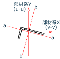
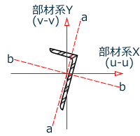
アンクル断面が非対称で、BS 5950:2000テーブル25を使用する際には、2つの主軸であるu-uおよびv-v、2つの幾何学軸であるa-aおよびb-bの、4つの軸を考慮する必要があります。v-v軸の有効長さはLVVパラメータから取得されますが、未指定の場合はLY · KYとなります。a-a軸とb-b軸は、アングルのどの脚が接合部に固定されるかで決まり、LEGパラメータにより設定する必要があります。LEGパラメータの詳細については、5B.6節を参照してください。a-a軸における有効長さはLY · KYとなり、b-b軸における有効長さはLZ · KZとなります。
次の図は、STまたはRAの設定によって定義されるアングルの軸を示しています。アングルは長脚において接合されています(a-a軸は長脚に対して平行となります)。