D13.D.5 2DElements: Slabs, Walls, and Shells
In general, the calculation of reinforcement for two dimensional elements (i.e., slabs, walls, and shells) is performed two times: once according to conditions of strength and again according to limiting of width of cracks. In reinforcement calculations for strength conditions (i.e., the first limit state), design load values must be used. In reinforcement calculations for crack width limitation (i.e., the second limit state), characteristic (i.e., normative or service) load values are used. Using the multiple analysis capability of STAAD.Pro allows you to carry out both calculations in a single analysis and design run.
Symmetric or non symmetric reinforcement of elements is calculated according to either first or second limit states by using the STA parameter.
It is necessary to pay close attention to the arrangement of local axis of the element with respect to the direction of reinforcement for the calculation of reinforcement. This is controlled using the CL and CRA parameters, as shown in the following figure.
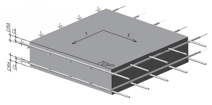

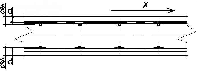
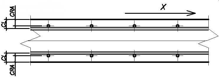
Russian concrete design parameters CL and CRA
An example output of reinforcement calculations:
                                 SLAB/WALL DESIGN RESULTS
                  (by stresses in local axes for limitation of crack width)
---------------------------------------------------------------------------------------------
  Element    Asx       Mx      Nx      Load. N.     Asy           My      Ny       Load N.
           sq.cm/m   kNm/m    kN/m       (X)       sq.cm/m      kNm/m    kN/m        (Y)
----------------------------------------------------------------------------------------------
60  TOP      0.00     *4.9     0.0        1	   0.00        *4.5     0.0        1
    BOT      3.53     *9.9     0.0        3	   3.46        *8.9     0.0        3
61  TOP      0.00     *5.3     0.0        1	   0.00        *4.7     0.0        1
    BOT      3.87    *10.7     0.0        3	   3.65        *9.4     0.0        3
62  TOP      0.00     *5.6     0.0        1	   0.00        *4.8     0.0        1
    BOT      4.10    *11.2     0.0        3	   3.77        *9.6     0.0        3
Where:
| Result | Description |
|---|---|
| Element | number of finite element,
("top" zone of member is determined by positive direction of local axis, Z) |
| Asx | intensity of reinforcing in the longitudinal direction (parallel to the local axis, X), sq.cm/m |
| Mx | distributed bending moment in respect to the local axis, Y, kNm/m |
| Nx | distributed longitudinal force directed parallel to the axis X, kNm/m |
| Load N.(X) | number of loading version, determining intensity of reinforcing in the longitudinal direction |
| Asy | intensity of reinforcing in the transverse direction (parallel to the local axis Y), sq.cm/m |
| My | distributed bending moment in respect to the local axis X kNm/m |
| Ny | distributed longitudinal force directed parallel to the local axis Y kN/m |
| Load N.(Y) | number of loading version, determining intensity of reinforcing in the transverse direction |
