EX. US-28 Calculation of Modes and Frequencies of a Bridge
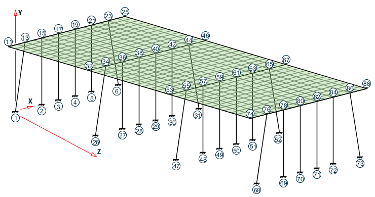
This example demonstrates the input required for obtaining the modes and frequencies of the skewed bridge shown in the figure below. The structure consists of piers, pier-cap girders and a deck slab.
This problem is installed with the program by default to C:\Users\Public\Public Documents\STAAD.Pro CONNECT Edition\Samples\Sample Models\US\US-28 Calculation of Modes and Frequencies of a Bridge.std when you install the program.
STAAD SPACE FREQUENCIES OF VIBRATION OF A SKEWED BRIDGE
Every STAAD input file has to begin with the word STAAD. The word SPACE signifies that the structure is a space frame and the geometry is defined through X, Y and Z axes. The remainder of the words forms a title to identify this project.
IGNORE LIST
Further below in this file, we will call element lists in which some element numbers may not actually be present in the structure. We do so because it minimizes the effort involved in fetching the desired elements and reduces the size of the respective commands. To prevent the program from treating that condition (referring to elements which do not exist) as an error, the above command is required.
UNIT METER KN
The units for the data that follows are specified above.
    JOINT COORDINATES
    1 0 0 0; 2 4 0 0; 3 6.5 0 0; 4 9 0 0; 5 11.5 0 0; 6 15.5 0 0;
    11 -1 10 0 25 16.5 10 0
    REPEAT ALL 3 4 0 14
For joints 1 through 6, the joint number followed by the X, Y and Z coordinates are specified first.
Next, using the coordinates of joints 11 and 25 as the basis, joints 12 through 24 are generated using linear interpolation.
Following this, using the data of these 21 joints (1 through 6 and 11 through 25), 63 new joints are generated. To achieve this, the X coordinate of these 21 joints is incremented by 4 meters and the Z coordinate is incremented by 14 meters, in 3 successive operations.
The REPEAT ALL command is used for the generation. Details of this command is available in TR.11 ジョイント座標の設定 . The results of the generation may be visually verified using STAAD.Pro's graphical viewing facilities.
    MEMBER INCI
    1 1 13 ; 2 2 15 ; 3 3 17 ; 4 4 19 ; 5 5 21 ; 6 6 23
    26 26 34 ; 27 27 36 ; 28 28 38 ; 29 29 40 ; 30 30 42 ; 31 31 44
    47 47 55 ; 48 48 57 ; 49 49 59 ; 50 50 61 ; 51 51 63 ; 52 52 65
    68 68 76 ; 69 69 78 ; 70 70 80 ; 71 71 82 ; 72 72 84 ; 73 73 86
The member connectivity data (joint numbers between which members are connected) is specified for the 24 columns for the structure. The above method, where the member number is followed by the 2 node numbers, is the explicit definition method. No generation is involved here.
    101 11 12 114
    202 32 33 215
    303 53 54 316
    404 74 75 417
The member connectivity data is specified for the pier cap beams for the structure. The above method is a combination of explicit definition and generation. For example, member 101 is defined as connected between 11 & 12. Then, by incrementing those nodes by 1 unit at a time (which is the default increment), the incidences of members 102 to 114 are generated. Similarly, we create members 202 to 215, 303 to 316, and, 404 to 417.
    DEFINE MESH
    A JOINT 11
    B JOINT 25
    C JOINT 46
    D JOINT 32
    E JOINT 67
    F JOINT 53
    G JOINT 88
    H JOINT 74
The next step is to generate the deck slab which will be modeled using plate elements. For this, we use a technique called mesh generation. Mesh generation is a process of generating several "child" elements from a "parent" or "super" element. The above set of commands defines the corner nodes of the super-element. Details of the above can be found in TR.14.2 要素メッシュの生成.
Note that instead of elaborately defining the coordinates of the corner nodes of the super-elements, we have taken advantage of the fact that the coordinates of these joints (A through H) have already been defined or generated earlier. Thus, A is the same as joint 11 while D is the same as joint 32. Alternatively, we could have defined the super-element nodes as A -1 10 0 ; B 16.5 10 0 ; C 20.5 10 14 ; D 3 10 14 ; etc.
    GENERATE ELEMENT
    MESH ABCD 14 12
    MESH DCEF 14 12
    MESH FEGH 14 12
The above lines are the instructions for generating the "child" elements from the super-elements. For example, from the super-element bound by the corners A, B, C and D (which in turn are nodes 11, 25, 46 and 32), we generate a total of 14X12=168 elements, with 14 divisions along the edges AB and CD, and 12 along the edges BC and DA. These are the elements which make up the first span.
Similarly, 168 elements are created for the 2nd span, and another 168 for the 3rd span.
It may be noted here that we have taken great care to ensure that the resulting elements and the piercap beams form a perfect fit. In other words, there is no overlap between the two in a manner that nodes of the beams are at a different point in space than nodes of elements. At every node along their common boundary, plates and beams are properly connected. This is absolutely essential to ensure proper transfer of load and stiffness from beams to plates and vice versa. The tools in the user interface may be used to confirm that beam-plate connectivity is proper for this model.
    START GROUP DEFINITION
    MEMBER
    _GIRDERS 101 TO 114 202 TO 215 303 TO 316 404 TO 417
    _PIERS 1 TO 6 26 TO 31 47 TO 52 68 TO 73
    ELEMENT
    _P1 447 TO 450 454 TO 457 461 TO 464 468 TO 471
    _P2 531 TO 534 538 TO 541 545 TO 548 552 TO 555
    _P3 615 TO 618 622 TO 625 629 TO 632 636 TO 639
    _P4 713 TO 716 720 TO 723 727 TO 730 734 TO 737
    _P5 783 TO 786 790 TO 793 797 TO 800 804 TO 807
    _P6 881 TO 884 888 TO 891 895 TO 898 902 TO 905
    END GROUP DEFINITION
The above block of data is referred to as formation of groups. Group names are a mechanism by which a single moniker can be used to refer to a cluster of entities, such as members. For our structure, the piercap beams are being grouped to a name called GIRDERS, the pier columns are assigned the name PIERS, and so on. For the deck, a few selected elements are chosen into a few selective groups. The reason is that these elements happen to be right beneath wheels of vehicles whose weight will be used in the frequency calculation.
    MEMBER PROPERTY
    _GIRDERS PRIS YD 0.6 ZD 0.6
    _PIERS PRIS YD 1.0
Member properties are assigned as prismatic rectangular sections for the girders, and prismatic circular sections for the columns.
    ELEMENT PROPERTY
    YRA 9 11 TH 0.375
The plate elements of the deck slab, which happen to be at a Y elevation of 10 metres (between a YRANGE of 9 metres and 11 metres) are assigned a thickness of 375 mms.
    UNIT KNS MMS
    DEFINE MATERIAL START
    ISOTROPIC CONCRETE
    E 21.0
    POISSON 0.17
    DENSITY 2.36158e-008
    ALPHA 5e-006
    DAMP 0.05
    G 9.25
    TYPE CONCRETE
    STRENGTH FCU 0.0275
    END DEFINE MATERIAL
    CONSTANTS
    MATERIAL CONCRETE ALL
The Modulus of elasticity (E) is set to 21000 N/sq.mm for all members. The keyword CONSTANTS has to precede this data. Built-in default value for Poisson's ratio for concrete is also assigned to ALL members and elements.
    UNIT KNS METER
    CONSTANTS
    DENSITY 24 ALL
Following a change of units, density of concrete is specified.
    SUPPORTS
    1 TO 6 26 TO 31 47 TO 52 68 TO 73 FIXED
The base nodes of the piers are fully restrained (FIXED supports).
CUT OFF MODE SHAPE 65
Theoretically, a structure has as many modes of vibration as the number of degrees of freedom in the model. However, the limitations of the mathematical process used in extracting modes may limit the number of modes that can actually be extracted. In a large structure, the extraction process can also be very time consuming. Further, not all modes are of equal importance. (One measure of the importance of modes is the participation factor of that mode.) In many cases, the first few modes may be sufficient to obtain a significant portion of the total dynamic response.
Due to these reasons, in the absence of any explicit instruction, STAAD calculates only the first 6 modes. This is like saying that the command CUT OFF MODE SHAPE 6 has been specified.
If the inspection of the first 6 modes reveals that the overall vibration pattern of the structure has not been obtained, one may ask STAAD to compute a larger (or smaller) number of modes with the help of this command. The number that follows this command is the number of modes being requested. In our example, we are asking for 65 modes by specifying CUT OFF MODE SHAPE 65.
    UNIT KGS METER
    LOAD 1 FREQUENCY CALCULATION
    SELFWEIGHT X 1.0
    SELFWEIGHT Y 1.0
    SELFWEIGHT Z 1.0
    * PERMANENT WEIGHTS ON DECK
    ELEMENT LOAD
    YRA 9 11 PR GX 200
    YRA 9 11 PR GY 200
    YRA 9 11 PR GZ 200
    * VEHICLES ON SPANS - ONLY Y & Z EFFECT CONSIDERED
    ELEMENT LOAD
    _P1 PR GY 700
    _P2 PR GY 700
    _P3 PR GY 700
    _P4 PR GY 700
    _P5 PR GY 700
    _P6 PR GY 700
    _P1 PR GZ 700
    _P2 PR GZ 700
    _P3 PR GZ 700
    _P4 PR GZ 700
    _P5 PR GZ 700
    _P6 PR GZ 700
The mathematical method that STAAD uses is called the eigen extraction method. Some information on this is available in G.17.3 Dynamic Analysis . The method involves 2 matrices - the stiffness matrix, and the mass matrix.
The stiffness matrix, usually called the [K] matrix, is assembled using data such as member and element lengths, member and element properties, modulus of elasticity, Poisson's ratio, member and element releases, member offsets, support information, etc.
For assembling the mass matrix, called the [M] matrix, STAAD uses the load data specified in the load case in which the MODAL CAL REQ command is specified. So, some of the important aspects to bear in mind are :
-
The input you specify is weights, not masses. Internally, STAAD will convert weights to masses by dividing the input by "g", the acceleration due to gravity.
-
If the structure is declared as a PLANE frame, there are 2 possible directions of vibration - global X, and global Y. If the structure is declared as a SPACE frame, there are 3 possible directions - global X, global Y and global Z. However, this does not guarantee that STAAD will automatically consider the masses for vibration in all the available directions.
You have control over and are responsible for specifying the directions in which the masses ought to vibrate. In other words, if a weight is not specified along a certain direction, the corresponding degrees of freedom (such as for example, global X at node 34 hypothetically) will not receive a contribution in the mass matrix. The mass matrix is assembled using only the masses from the weights and directions you specify.
In our example, notice that we are specifying the selfweight along global X, Y and Z directions. Similarly, a 200 kg/sq.m pressure load is also specified along all 3 directions on the deck.
But for the truck loads, we choose to apply it on just a few elements in the global Y and Z directions only. The reasoning is something like - for the X direction, the mass is not capable of vibrating because the tires allow the truck to roll along X. Remember, this is just a demonstration example, not necessarily what you may want to do.
The point we want to illustrate is that if you want to restrict a certain weight to certain directions only, all you need to do is not provide the directions in which those weights cannot vibrate in.
-
As much as possible, provide absolute values for the weights. STAAD is programmed to algebraically add the weights at nodes. So, if some weights are specified as positive numbers and others as negative, the total weight at a given node is the algebraic summation of all the weights in the global directions at that node and the mass is then derived from this algebraic resultant.
MODAL CALCULATION REQUESTED
This is the command which tells the program that frequencies and modes should be calculated. It is specified inside a load case. In other words, this command accompanies the loads that are to be used in generating the mass matrix.
Frequencies and modes have to be calculated also when dynamic analysis such as response spectrum or time history analysis is carried out. But in such analyses, the MODAL CALCULATION REQUESTED command is not explicitly required. When STAAD encounters the commands for response spectrum (see example 11) and time history (see examples 16 and 22), it automatically will carry out a frequency extraction without the help of the MODAL .. command.
PERFORM ANALYSIS
This initiates the processes which are required to obtain the frequencies. Frequencies, periods and participation factors are automatically reported in the output file when the operation is completed.
FINISH
This terminates the STAAD run.
Input File
STAAD SPACE FREQUENCIES OF VIBRATION OF A SKEWED BRIDGE
IGNORE LIST
UNIT METER KN
JOINT COORDINATES
1 0 0 0; 2 4 0 0; 3 6.5 0 0; 4 9 0 0; 5 11.5 0 0; 6 15.5 0 0;
11 -1 10 0 25 16.5 10 0
REPEAT ALL 3 4 0 14
MEMBER INCI
1 1 13 ; 2 2 15 ; 3 3 17 ; 4 4 19 ; 5 5 21 ; 6 6 23
26 26 34 ; 27 27 36 ; 28 28 38 ; 29 29 40 ; 30 30 42 ; 31 31 44
47 47 55 ; 48 48 57 ; 49 49 59 ; 50 50 61 ; 51 51 63 ; 52 52 65
68 68 76 ; 69 69 78 ; 70 70 80 ; 71 71 82 ; 72 72 84 ; 73 73 86
101 11 12 114
202 32 33 215
303 53 54 316
404 74 75 417
DEFINE MESH
A JOINT 11
B JOINT 25
C JOINT 46
D JOINT 32
E JOINT 67
F JOINT 53
G JOINT 88
H JOINT 74
GENERATE ELEMENT
MESH ABCD 14 12
MESH DCEF 14 12
MESH FEGH 14 12
START GROUP DEFINITION
MEMBER
_GIRDERS 101 TO 114 202 TO 215 303 TO 316 404 TO 417
_PIERS 1 TO 6 26 TO 31 47 TO 52 68 TO 73
ELEMENT
_P1 447 TO 450 454 TO 457 461 TO 464 468 TO 471
_P2 531 TO 534 538 TO 541 545 TO 548 552 TO 555
_P3 615 TO 618 622 TO 625 629 TO 632 636 TO 639
_P4 713 TO 716 720 TO 723 727 TO 730 734 TO 737
_P5 783 TO 786 790 TO 793 797 TO 800 804 TO 807
_P6 881 TO 884 888 TO 891 895 TO 898 902 TO 905
END GROUP DEFINITION
MEMBER PROPERTY
_GIRDERS PRIS YD 0.6 ZD 0.6
_PIERS PRIS YD 1.0
ELEMENT PROPERTY
YRA 9 11 TH 0.375
UNIT KNS MMS
DEFINE MATERIAL START
ISOTROPIC CONCRETE
E 21.0
POISSON 0.17
DENSITY 2.36158e-008
ALPHA 5e-006
DAMP 0.05
G 9.25
TYPE CONCRETE
STRENGTH FCU 0.0275
END DEFINE MATERIAL
CONSTANTS
MATERIAL CONCRETE ALL
SUPPORTS
1 TO 6 26 TO 31 47 TO 52 68 TO 73 FIXED
CUT OFF MODE SHAPE 65
UNIT KGS METER
LOAD 1 FREQUENCY CALCULATION
SELFWEIGHT X 1.0
SELFWEIGHT Y 1.0
SELFWEIGHT Z 1.0
* PERMANENT WEIGHTS ON DECK
ELEMENT LOAD
YRA 9 11 PR GX 200
YRA 9 11 PR GY 200
YRA 9 11 PR GZ 200
* VEHICLES ON SPANS - ONLY Y & Z EFFECT CONSIDERED
ELEMENT LOAD
_P1 PR GY 700
_P2 PR GY 700
_P3 PR GY 700
_P4 PR GY 700
_P5 PR GY 700
_P6 PR GY 700
_P1 PR GZ 700
_P2 PR GZ 700
_P3 PR GZ 700
_P4 PR GZ 700
_P5 PR GZ 700
_P6 PR GZ 700
MODAL CALCULATION REQUESTED
PERFORM ANALYSIS
FINISH
STAAD Output File
PAGE NO. 1 **************************************************** * * * STAAD.Pro CONNECT Edition * * Version 22.10.00.*** * * Proprietary Program of * * Bentley Systems, Inc. * * Date= MAR 24, 2022 * * Time= 9:46:19 * * * * Licensed to: Bentley Systems Inc * **************************************************** 1. STAAD SPACE FREQUENCIES OF VIBRATION OF A SKEWED BRIDGE INPUT FILE: US-28 Calculation of Modes and Frequencies of a Bridge.STD 2. IGNORE LIST 3. UNIT METER KN 4. JOINT COORDINATES 5. 1 0 0 0; 2 4 0 0; 3 6.5 0 0; 4 9 0 0; 5 11.5 0 0; 6 15.5 0 0 6. 11 -1 10 0 25 16.5 10 0 7. REPEAT ALL 3 4 0 14 8. MEMBER INCI 9. 1 1 13 ; 2 2 15 ; 3 3 17 ; 4 4 19 ; 5 5 21 ; 6 6 23 10. 26 26 34 ; 27 27 36 ; 28 28 38 ; 29 29 40 ; 30 30 42 ; 31 31 44 11. 47 47 55 ; 48 48 57 ; 49 49 59 ; 50 50 61 ; 51 51 63 ; 52 52 65 12. 68 68 76 ; 69 69 78 ; 70 70 80 ; 71 71 82 ; 72 72 84 ; 73 73 86 13. 101 11 12 114 14. 202 32 33 215 15. 303 53 54 316 16. 404 74 75 417 17. DEFINE MESH 18. A JOINT 11 19. B JOINT 25 20. C JOINT 46 21. D JOINT 32 22. E JOINT 67 23. F JOINT 53 24. G JOINT 88 25. H JOINT 74 26. GENERATE ELEMENT 27. MESH ABCD 14 12 28. MESH DCEF 14 12 29. MESH FEGH 14 12 30. START GROUP DEFINITION 31. MEMBER 32. _GIRDERS 101 TO 114 202 TO 215 303 TO 316 404 TO 417 33. _PIERS 1 TO 6 26 TO 31 47 TO 52 68 TO 73 34. ELEMENT 35. _P1 447 TO 450 454 TO 457 461 TO 464 468 TO 471 36. _P2 531 TO 534 538 TO 541 545 TO 548 552 TO 555 37. _P3 615 TO 618 622 TO 625 629 TO 632 636 TO 639 38. _P4 713 TO 716 720 TO 723 727 TO 730 734 TO 737 FREQUENCIES OF VIBRATION OF A SKEWED BRIDGE -- PAGE NO. 2 39. _P5 783 TO 786 790 TO 793 797 TO 800 804 TO 807 40. _P6 881 TO 884 888 TO 891 895 TO 898 902 TO 905 41. END GROUP DEFINITION 42. MEMBER PROPERTY 43. _GIRDERS PRIS YD 0.6 ZD 0.6 44. _PIERS PRIS YD 1.0 45. ELEMENT PROPERTY 46. YRA 9 11 TH 0.375 47. UNIT KNS MMS 48. DEFINE MATERIAL START 49. ISOTROPIC CONCRETE 50. E 21.0 51. POISSON 0.17 52. DENSITY 2.36158E-008 53. ALPHA 5E-006 54. DAMP 0.05 55. G 9.25 56. TYPE CONCRETE 57. STRENGTH FCU 0.0275 58. END DEFINE MATERIAL 59. CONSTANTS 60. MATERIAL CONCRETE ALL 61. SUPPORTS 62. 1 TO 6 26 TO 31 47 TO 52 68 TO 73 FIXED 63. CUT OFF MODE SHAPE 65 64. UNIT KGS METER 65. LOAD 1 FREQUENCY CALCULATION 66. SELFWEIGHT X 1.0 67. SELFWEIGHT Y 1.0 68. SELFWEIGHT Z 1.0 69. * PERMANENT WEIGHTS ON DECK 70. ELEMENT LOAD 71. YRA 9 11 PR GX 200 72. YRA 9 11 PR GY 200 73. YRA 9 11 PR GZ 200 74. * VEHICLES ON SPANS - ONLY Y & Z EFFECT CONSIDERED 75. ELEMENT LOAD 76. _P1 PR GY 700 77. _P2 PR GY 700 78. _P3 PR GY 700 79. _P4 PR GY 700 80. _P5 PR GY 700 81. _P6 PR GY 700 82. _P1 PR GZ 700 83. _P2 PR GZ 700 84. _P3 PR GZ 700 85. _P4 PR GZ 700 86. _P5 PR GZ 700 87. _P6 PR GZ 700 88. MODAL CALCULATION REQUESTED 89. PERFORM ANALYSIS FREQUENCIES OF VIBRATION OF A SKEWED BRIDGE -- PAGE NO. 3 P R O B L E M S T A T I S T I C S ----------------------------------- NUMBER OF JOINTS 579 NUMBER OF MEMBERS 80 NUMBER OF PLATES 504 NUMBER OF SOLIDS 0 NUMBER OF SURFACES 0 NUMBER OF SUPPORTS 24 Using 64-bit analysis engine. SOLVER USED IS THE IN-CORE ADVANCED MATH SOLVER TOTAL PRIMARY LOAD CASES = 1, TOTAL DEGREES OF FREEDOM = 3330 TOTAL LOAD COMBINATION CASES = 0 SO FAR. *** NOTE: CAPACITY FOR MAXIMUM # 252 LOAD CASES IS ASSIGNED FOR PLATE LOAD. ** WARNING: PRESSURE LOADS ON ELEMENTS OTHER THAN PLATE ELEMENTS ARE IGNORED. ELEM.NO. 101 ** WARNING: PRESSURE LOADS ON ELEMENTS OTHER THAN PLATE ELEMENTS ARE IGNORED. ELEM.NO. 101 ** WARNING: PRESSURE LOADS ON ELEMENTS OTHER THAN PLATE ELEMENTS ARE IGNORED. ELEM.NO. 101 ***NOTE: MASSES DEFINED UNDER LOAD# 1 WILL FORM THE FINAL MASS MATRIX FOR DYNAMIC ANALYSIS. EIGEN METHOD : SUBSPACE ------------------------- NUMBER OF MODES REQUESTED = 65 NUMBER OF EXISTING MASSES IN THE MODEL = 1665 NUMBER OF MODES THAT WILL BE USED = 65 *** EIGENSOLUTION : ADVANCED METHOD *** FREQUENCIES OF VIBRATION OF A SKEWED BRIDGE -- PAGE NO. 4 CALCULATED FREQUENCIES FOR LOAD CASE 1 MODE FREQUENCY(CYCLES/SEC) PERIOD(SEC) 1 1.648 0.60681 2 2.622 0.38132 3 2.906 0.34409 4 3.783 0.26436 5 4.108 0.24345 6 4.423 0.22608 7 4.561 0.21927 8 4.725 0.21162 9 5.080 0.19684 10 7.277 0.13742 11 7.328 0.13647 12 7.454 0.13416 13 10.418 0.09599 14 10.818 0.09244 15 11.260 0.08881 16 11.377 0.08790 17 11.672 0.08567 18 11.945 0.08372 19 12.028 0.08314 20 12.209 0.08191 21 12.619 0.07925 22 13.823 0.07234 23 14.807 0.06754 24 14.920 0.06702 25 15.294 0.06539 26 17.489 0.05718 27 17.664 0.05661 28 17.937 0.05575 29 19.923 0.05019 30 20.116 0.04971 31 20.724 0.04825 32 20.817 0.04804 33 21.024 0.04756 34 21.340 0.04686 35 21.633 0.04623 36 22.002 0.04545 37 22.290 0.04486 38 23.393 0.04275 39 23.738 0.04213 40 24.235 0.04126 41 24.881 0.04019 42 25.690 0.03893 43 26.275 0.03806 44 26.700 0.03745 45 27.124 0.03687 46 27.610 0.03622 47 28.063 0.03563 48 29.272 0.03416 49 29.866 0.03348 50 30.118 0.03320 51 31.309 0.03194 FREQUENCIES OF VIBRATION OF A SKEWED BRIDGE -- PAGE NO. 5 CALCULATED FREQUENCIES FOR LOAD CASE 1 MODE FREQUENCY(CYCLES/SEC) PERIOD(SEC) 52 31.832 0.03142 53 32.014 0.03124 54 32.312 0.03095 55 32.906 0.03039 56 33.204 0.03012 57 34.467 0.02901 58 35.270 0.02835 59 35.522 0.02815 60 35.766 0.02796 61 36.318 0.02753 62 36.919 0.02709 63 38.921 0.02569 64 39.189 0.02552 65 39.905 0.02506 MODAL WEIGHT (MODAL MASS TIMES g) IN KGS GENERALIZED MODE X Y Z WEIGHT 1 1.291934E+02 1.123418E+00 1.185768E+06 1.205497E+06 2 1.089784E+06 2.961298E+00 2.290601E+02 1.083499E+06 3 2.111306E-01 2.767724E+03 2.799804E+00 5.416754E+05 4 1.488365E+00 3.916563E+04 6.302102E+00 1.988939E+05 5 2.650657E-01 4.869465E+02 5.916391E+02 1.348431E+05 6 5.553985E+02 7.047738E+02 2.743600E+02 8.887365E+04 7 1.872127E+01 3.523236E+05 3.255370E+00 7.402632E+04 8 5.441681E+00 2.711803E+05 8.530684E+00 7.667142E+04 9 5.838996E+03 1.713501E+03 2.233780E+03 6.923635E+04 10 4.436158E+00 1.508718E+03 4.951104E-01 4.324923E+04 11 4.522846E+00 6.614279E+02 1.224734E+00 4.305570E+04 12 2.322126E-01 4.156161E+02 7.878947E-01 3.944772E+04 13 3.968726E+01 2.882564E+00 6.818221E+03 1.532777E+05 14 2.085091E-01 1.298117E+02 1.097372E+02 7.154577E+04 15 2.752974E-02 4.303212E+03 1.232103E+02 4.541365E+04 16 7.726809E+00 7.931786E+01 1.710543E+02 5.083780E+04 17 9.187165E+00 2.295488E+00 5.600056E-01 5.231609E+04 18 1.289274E+02 1.227798E+01 1.533801E+02 8.841806E+04 19 3.797408E-01 3.151484E+01 4.203883E+00 4.601297E+04 20 9.958856E+00 7.524730E+01 1.835670E+01 7.466321E+04 21 8.006146E-01 2.974809E+00 4.620779E+00 7.378575E+04 22 1.242891E+02 1.356224E-01 1.727536E+00 4.087678E+05 23 6.938982E+00 4.623798E+01 8.257328E+01 6.864460E+04 24 4.653175E-01 1.849773E+02 6.876842E+00 5.597259E+04 25 8.352727E+00 1.093998E+01 2.047659E+02 4.884299E+04 26 3.879229E-01 2.187085E+03 5.145218E-03 2.890765E+04 27 8.086885E+00 3.229583E+02 9.429697E-01 3.202062E+04 FREQUENCIES OF VIBRATION OF A SKEWED BRIDGE -- PAGE NO. 6 28 2.443751E+00 1.315502E+04 2.609740E-01 2.997395E+04 29 6.642359E+02 6.512258E+03 5.785467E+01 3.489561E+04 30 3.896515E+01 4.236802E+04 5.583570E+00 3.273818E+04 31 2.124308E+02 2.362562E+02 6.791406E-01 2.856038E+04 32 2.501307E+01 4.154716E+04 1.610248E-03 3.529900E+04 33 9.944393E+00 2.188227E+03 7.002218E-01 3.488091E+04 34 1.354775E+01 1.273812E+02 9.929674E+00 3.662762E+04 35 2.684736E+00 5.035591E+03 2.202823E+00 4.255654E+04 36 3.584198E-01 7.349881E+00 1.032835E+00 5.119778E+04 37 1.674724E+00 2.647461E+04 8.112263E-01 4.340583E+04 38 1.234580E+00 8.274586E+01 1.831619E-02 1.919433E+04 39 1.177019E-02 3.952054E+02 4.526474E-01 1.820400E+04 40 2.510682E-03 2.913923E+01 2.643008E-04 4.236454E+05 41 1.752055E+00 1.750469E+03 1.098303E+01 4.948152E+04 42 3.172853E-01 5.576266E+04 1.029036E-01 7.029313E+04 43 4.088524E+00 7.230284E+02 1.647904E+00 7.840900E+04 44 6.792844E-03 6.810530E+02 2.323051E-02 7.748353E+04 45 1.286032E-02 2.969021E+02 6.276731E-04 1.698166E+05 46 3.915110E-01 1.842050E+03 1.016859E-02 2.296592E+04 47 1.222720E+01 2.250049E+00 1.763239E+00 1.408108E+04 48 5.796924E-03 4.479735E+03 7.592468E-02 2.885324E+04 49 3.062960E+00 1.622740E+01 2.516519E-01 4.734347E+04 50 5.381654E-01 2.109875E-02 3.715996E+00 4.275013E+04 51 6.988027E-03 1.414464E+02 1.037723E-01 2.721877E+04 52 3.120314E-01 2.679203E+00 8.601323E-01 4.346363E+04 53 7.712285E-01 1.227296E+03 2.159809E-01 3.644744E+04 54 1.092693E+01 6.309261E+01 4.335824E+00 4.837668E+04 55 4.389927E-01 2.654929E+02 5.449158E+00 2.579368E+04 56 1.697410E-01 8.013763E+02 1.519167E-02 3.565397E+04 57 5.812394E-01 1.003674E+02 1.297763E+00 3.819235E+04 58 6.155775E+00 1.623267E+03 1.175780E+01 4.182908E+04 59 3.892790E+00 1.515229E+01 1.764828E+01 3.953446E+04 60 7.019893E+00 5.144657E+02 4.912786E+01 5.200588E+04 61 5.075761E+01 1.707431E+03 3.625510E+01 1.190568E+04 62 2.640553E+01 3.154571E+03 1.681321E+01 1.455738E+04 63 1.733228E-01 5.382845E+02 4.096147E-01 7.325642E+04 64 1.024425E-01 3.773902E+03 1.746056E-01 6.231664E+04 65 7.508947E+00 2.059276E+03 1.501086E+01 3.298603E+04 FREQUENCIES OF VIBRATION OF A SKEWED BRIDGE -- PAGE NO. 7 MASS PARTICIPATION FACTORS MASS PARTICIPATION FACTORS IN PERCENT -------------------------------------- MODE X Y Z SUMM-X SUMM-Y SUMM-Z 1 0.01 0.00 99.04 0.012 0.000 99.042 2 99.14 0.00 0.02 99.152 0.000 99.061 3 0.00 0.23 0.00 99.152 0.232 99.061 4 0.00 3.27 0.00 99.152 3.503 99.062 5 0.00 0.04 0.05 99.152 3.544 99.111 6 0.05 0.06 0.02 99.202 3.602 99.134 7 0.00 29.43 0.00 99.204 33.030 99.134 8 0.00 22.65 0.00 99.205 55.681 99.135 9 0.53 0.14 0.19 99.736 55.824 99.322 10 0.00 0.13 0.00 99.736 55.950 99.322 11 0.00 0.06 0.00 99.737 56.005 99.322 12 0.00 0.03 0.00 99.737 56.040 99.322 13 0.00 0.00 0.57 99.740 56.040 99.891 14 0.00 0.01 0.01 99.740 56.051 99.901 15 0.00 0.36 0.01 99.740 56.411 99.911 16 0.00 0.01 0.01 99.741 56.417 99.925 17 0.00 0.00 0.00 99.742 56.417 99.925 18 0.01 0.00 0.01 99.754 56.418 99.938 19 0.00 0.00 0.00 99.754 56.421 99.938 20 0.00 0.01 0.00 99.754 56.427 99.940 21 0.00 0.00 0.00 99.755 56.428 99.940 22 0.01 0.00 0.00 99.766 56.428 99.940 23 0.00 0.00 0.01 99.766 56.431 99.947 24 0.00 0.02 0.00 99.767 56.447 99.948 25 0.00 0.00 0.02 99.767 56.448 99.965 26 0.00 0.18 0.00 99.767 56.630 99.965 27 0.00 0.03 0.00 99.768 56.657 99.965 28 0.00 1.10 0.00 99.768 57.756 99.965 29 0.06 0.54 0.00 99.829 58.300 99.970 30 0.00 3.54 0.00 99.832 61.839 99.970 31 0.02 0.02 0.00 99.852 61.859 99.971 32 0.00 3.47 0.00 99.854 65.329 99.971 33 0.00 0.18 0.00 99.855 65.512 99.971 34 0.00 0.01 0.00 99.856 65.522 99.971 35 0.00 0.42 0.00 99.856 65.943 99.972 36 0.00 0.00 0.00 99.856 65.944 99.972 37 0.00 2.21 0.00 99.856 68.155 99.972 38 0.00 0.01 0.00 99.857 68.162 99.972 39 0.00 0.03 0.00 99.857 68.195 99.972 40 0.00 0.00 0.00 99.857 68.197 99.972 41 0.00 0.15 0.00 99.857 68.343 99.973 42 0.00 4.66 0.00 99.857 73.001 99.973 43 0.00 0.06 0.00 99.857 73.061 99.973 44 0.00 0.06 0.00 99.857 73.118 99.973 45 0.00 0.02 0.00 99.857 73.143 99.973 46 0.00 0.15 0.00 99.857 73.297 99.973 47 0.00 0.00 0.00 99.858 73.297 99.973 48 0.00 0.37 0.00 99.858 73.671 99.973 49 0.00 0.00 0.00 99.859 73.673 99.973 50 0.00 0.00 0.00 99.859 73.673 99.973 51 0.00 0.01 0.00 99.859 73.685 99.973 52 0.00 0.00 0.00 99.859 73.685 99.973 53 0.00 0.10 0.00 99.859 73.787 99.973 54 0.00 0.01 0.00 99.860 73.793 99.974 55 0.00 0.02 0.00 99.860 73.815 99.974 56 0.00 0.07 0.00 99.860 73.882 99.974 FREQUENCIES OF VIBRATION OF A SKEWED BRIDGE -- PAGE NO. 8 MASS PARTICIPATION FACTORS IN PERCENT -------------------------------------- MODE X Y Z SUMM-X SUMM-Y SUMM-Z 57 0.00 0.01 0.00 99.860 73.890 99.974 58 0.00 0.14 0.00 99.860 74.026 99.975 59 0.00 0.00 0.00 99.861 74.027 99.977 60 0.00 0.04 0.00 99.861 74.070 99.981 61 0.00 0.14 0.00 99.866 74.212 99.984 62 0.00 0.26 0.00 99.868 74.476 99.985 63 0.00 0.04 0.00 99.868 74.521 99.985 64 0.00 0.32 0.00 99.868 74.836 99.985 65 0.00 0.17 0.00 99.869 75.008 99.987 90. FINISH FREQUENCIES OF VIBRATION OF A SKEWED BRIDGE -- PAGE NO. 9 *********** END OF THE STAAD.Pro RUN *********** **** DATE= MAR 24,2022 TIME= 9:46:22 **** ************************************************************ * For technical assistance on STAAD.Pro, please visit * * http://www.bentley.com/en/support/ * * * * Details about additional assistance from * * Bentley and Partners can be found at program menu * * Help->Technical Support * * * * Copyright (c) Bentley Systems, Inc. * * http://www.bentley.com * ************************************************************
Understanding the output
After the analysis is complete, look at the output file. (This file can be viewed by selecting the Analysis Output tool in the View group on the Utilities ribbon tab).
-
Mode number and corresponding frequencies and periods
Since we asked for 65 modes, we obtain a report, a portion of which is as shown:
Table 1. Calculated Frequencies for Load Case 1 Mode Frequency (Cycles/Sec)
Period (Sec)
Accuracy 1 1.636 0.61111 1.344E-16 2 2.602 0.38433 0.000E+00 3 2.882 0.34695 8.666E-16 4 3.754 0.26636 0.000E+00 5 4.076 0.24532 3.466E-16 6 4.373 0.22870 6.025E-16 7 4.519 0.22130 5.641E-16 8 4.683 0.21355 5.253E-16 9 5.028 0.19889 0.000E+00 10 7.189 0.13911 8.916E-16 11 7.238 0.13815 0.000E+00 12 7.363 0.13582 0.000E+00 -
Participation factors in Percentage
Table 2. Mass Participation Factors in Percent Mode X Y Z ΣX ΣY ΣZ 1 0.01 0.00 99.04 0.012 0.000 99.042 2 99.14 0.00 0.02 99.151 0.000 99.061 3 0.00 0.23 0.00 99.151 0.229 99.062 4 0.00 3.27 0.00 99.151 3.496 99.062 5 0.00 0.04 0.05 99.151 3.536 99.112 6 0.05 0.04 0.02 99.202 3.575 99.135 7 0.00 26.42 0.00 99.204 30.000 99.135 8 0.00 25.59 0.00 99.204 55.587 99.136 9 0.53 0.15 0.19 99.735 55.740 99.326 10 0.00 0.13 0.00 99.736 55.871 99.326 11 0.00 0.06 0.00 99.736 55.927 99.326 12 0.00 0.04 0.00 99.736 55.969 99.326 In the explanation earlier for the CUT OFF MODE command, we said that one measure of the importance of a mode is the participation factor of that mode. We can see from the above report that for vibration along Z direction, the first mode has a 99.04 percent participation. It is also apparent that the 7th mode is primarily a Y direction mode with a 26.42% participation along Y and 0 in X and Z.
The ΣX, ΣY and ΣZ columns show the cumulative value of the participation of all the modes up to and including a given mode (Corresponding to the SUMM-X, SUMM-Y, and SUMM-Z reported in the output, respectively). One can infer from those terms that if one is interested in 95% participation along X, the first 2 modes are sufficient.
But for the Y direction, even with 10 modes, we barely obtained 60%. The reason for this can be understood by an examination of the nature of the structure. The deck slab is capable of vibrating in several low energy and primarily vertical direction modes. The out-of-plane flexible nature of the slab enables it to vibrate in a manner resembling a series of wave like curves. Masses on either side of the equilibrium point have opposing eigenvector values leading to a lot of cancellation of the contribution from the respective masses. Localized modes, where small pockets in the structure undergo flutter due to their relative weak stiffness compared to the rest of the model, also result in small participation factors.
-
After the analysis is completed, select Post-processing from the mode menu. This screen contains facilities for graphically examining the shape of the mode in static and animated views. The Dynamics page on the left side of the screen is available for viewing the shape of the mode statically. The Animation option of the Results menu can be used for animating the mode. The mode number can be selected from the Loads and Results tab of the Diagrams dialog box which opens when the Animation option is chosen. The size to which the mode is drawn is controlled using the Scales tab of the Diagrams dialog box.