EX. UK-18 Stress Calculation for Plate Elements
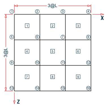
This is an example which demonstrates the calculation of principal stresses on a finite element.
This problem is installed with the program by default to C:\Users\Public\Public Documents\STAAD.Pro CONNECT Edition\Samples\Sample Models\UK\UK-18 Stress Calculation for Plate Elements.STD when you install the program.
Where:
- L = 3 m
Fixed Supports at Joints 1, 2, 3, 4, 5, 9, 13
Load intensity = 2000 Kn/sq.m in - Y direction
Actual input is shown in bold lettering followed by explanation.
    STAAD SPACE SAMPLE CALCULATION FOR
    * ELEMENT STRESSES
Every input has to start with the term STAAD. The word SPACE signifies that the structure is a space frame (3-D structure).
UNIT METER KNS
Defines the input units for the data that follows.
    JOINT COORDINATES
    1 0 0 0 4 9 0 0
    REPEAT 3 0 0 3
Joint number followed by X, Y and Z coordinates are provided above. The REPEAT command is used to generate coordinates of joints 5 to 16 based on the pattern of joints 1 to 4.
    ELEMENT INCIDENCE
    1 1 5 6 2 TO 3
    REPEAT 2 3 4
Element connectivities of elements 1 to 3 are defined first, based on which, the connectivities of elements 4 to 9 are generated.
    ELEMENT PROPERTIES
    1 TO 9 THICK 0.25
Elements 1 to 9 have a thickness of 0.25 m.
    UNIT MMS
    DEFINE MATERIAL START
    ISOTROPIC CONCRETE
    E 21.0
    POISSON 0.17
    DENSITY 2.36158e-008
    ALPHA 5e-006
    DAMP 0.05
    G 9.25
    TYPE CONCRETE
    STRENGTH FCU 0.0275
    END DEFINE MATERIAL
    CONSTANTS
    MATERIAL CONCRETE ALL
    UNIT METER
The DEFINE MATERIAL command is used to specify material properties and the CONSTANT is used to assign the material to all members.
    SUPPORT
    1 TO 4 5 9 13 FIXED
Fixed support conditions exist at the above mentioned joints.
    LOAD 1
    ELEMENT LOAD
    1 TO 9 PRESSURE -2000.0
A uniform pressure of 2000 Kn/sq.m is applied on all the elements. In the absence of an explicit direction specification, the load is assumed to act along the local Z axis. The negative value indicates that the load acts opposite to the positive direction of the local Z.
PERFORM ANALYSIS
The above command instructs the program to proceed with the analysis.
PRINT SUPPORT REACTION
The above command is self-explanatory.
    UNIT MMS
    PRINT ELEMENT STRESSES LIST 4
Element stresses at the centroid of the element are printed using the above command. The output includes membrane stresses, shear stresses, bending moments per unit width and principal stresses. The change of length unit from meter to mms indicates that the values will be printed in KN and MMs units.
FINISH
The STAAD run is terminated.
Calculation of principal stresses for element 4
Calculations are presented for the top surface only.
SX = 0.0 kN/mm2
SY = 0.0 kN/mm2
SXY = 0.0 kN/mm2
MX = 2,111.84 kN-mm/mm
MY = 10,726.22 kN-mm/m
MXY = 4,553.97 kN-mm/mm
S = 1/6t2 = 1/(6·2502) = 10,416.67mm2 (Section Modulus)
σx = SX + MX/S = 0.0 + 2,111.84/10,416.67 = 0.2027 kN/mm2
σy = SY + MY/S = 0.0 + 10,726.22/10,416.67 = 1.0297 kN/mm2
τxy = SXY + MXY/S = 0.0 + 4,553.97/10,416.67 = 0.4372 kN/mm2
SMax = (σx + σy)/2 + TMax = (0.2027 + 1.0297)/2 + 0.6018 = 1.218 kN/mm2
Say 1.22 kN/mm2
SMin = (σx + σy)/2 - TMax = (0.2027 + 1.0297)/2 - 0.6018 = 0.0144 kN/mm2
Say 0.01 kN/ mm2
Input File
STAAD SPACE SAMPLE CALCULATION FOR
* ELEMENT STRESSES
UNIT METER KNS
JOINT COORDINATES
1 0 0 0 4 9 0 0
REPEAT 3 0 0 3
ELEMENT INCIDENCE
1 1 5 6 2 TO 3
REPEAT 2 3 4
ELEMENT PROPERTIES
1 TO 9 THICK 0.25
UNIT MMS
DEFINE MATERIAL START
ISOTROPIC CONCRETE
E 21.0
POISSON 0.17
DENSITY 2.36158e-008
ALPHA 5e-006
DAMP 0.05
G 9.25
TYPE CONCRETE
STRENGTH FCU 0.0275
END DEFINE MATERIAL
CONSTANTS
MATERIAL CONCRETE ALL
UNIT METER
SUPPORT
1 TO 4 5 9 13 FIXED
LOAD 1
ELEMENT LOAD
1 TO 9 PRESSURE -2000.0
PERFORM ANALYSIS
PRINT SUPPORT REACTION
UNIT MMS
PRINT ELEMENT STRESSES LIST 4
FINISH
STAAD Output File
                                                                  PAGE NO.    1
             ****************************************************
             *                                                  *
             *           STAAD.Pro CONNECT Edition              *
             *           Version  22.10.00.***                  *
             *           Proprietary Program of                 *
             *           Bentley Systems, Inc.                  *
             *           Date=    MAR 24, 2022                  *
             *           Time=     9:44:28                      *
             *                                                  *
             *  Licensed to: Bentley Systems Inc                *
             ****************************************************
     1. STAAD SPACE SAMPLE CALCULATION FOR
INPUT FILE: UK-18 Stress Calculation for Plate Elements.STD
     2. * ELEMENT STRESSES
     3. UNIT METER KNS
     4. JOINT COORDINATES
     5. 1 0 0 0 4 9 0 0
     6. REPEAT 3 0 0 3
     7. ELEMENT INCIDENCE
     8. 1 1 5 6 2 TO 3
     9. REPEAT 2 3 4
    10. ELEMENT PROPERTIES
    11. 1 TO 9 THICK 0.25
    12. UNIT MMS
    13. DEFINE MATERIAL START
    14. ISOTROPIC CONCRETE
    15. E 21.0
    16. POISSON 0.17
    17. DENSITY 2.36158E-008
    18. ALPHA 5E-006
    19. DAMP 0.05
    20. G 9.25
    21. TYPE CONCRETE
    22. STRENGTH FCU 0.0275
    23. END DEFINE MATERIAL
    24. CONSTANTS
    25. MATERIAL CONCRETE ALL
    26. UNIT METER
    27. SUPPORT
    28. 1 TO 4 5 9 13 FIXED
    29. LOAD 1
    30. ELEMENT LOAD
    31. 1 TO 9 PRESSURE -2000.0
    32. PERFORM ANALYSIS
      SAMPLE CALCULATION FOR                                   -- PAGE NO.    2
    * ELEMENT STRESSES
            P R O B L E M   S T A T I S T I C S
            -----------------------------------
     NUMBER OF JOINTS         16  NUMBER OF MEMBERS       0
     NUMBER OF PLATES          9  NUMBER OF SOLIDS        0
     NUMBER OF SURFACES        0  NUMBER OF SUPPORTS      7
           Using 64-bit analysis engine.
           SOLVER USED IS THE IN-CORE ADVANCED MATH SOLVER
   TOTAL      PRIMARY LOAD CASES =     1, TOTAL DEGREES OF FREEDOM =      54
   TOTAL LOAD COMBINATION  CASES =     0  SO FAR.
   *** NOTE: CAPACITY FOR MAXIMUM #    252 LOAD CASES IS ASSIGNED FOR PLATE LOAD.
    33. PRINT SUPPORT REACTION
  SUPPORT  REACTION
      SAMPLE CALCULATION FOR                                   -- PAGE NO.    3
    * ELEMENT STRESSES
   SUPPORT REACTIONS -UNIT KNS  METE    STRUCTURE TYPE = SPACE
   -----------------
 JOINT  LOAD   FORCE-X   FORCE-Y   FORCE-Z     MOM-X     MOM-Y     MOM Z
      1    1      0.00  -1291.48      0.00   -348.06      0.00    348.06
      2    1      0.00   8700.82      0.00 -26485.08      0.00   -384.11
      3    1      0.00  37742.16      0.00 -87763.47      0.00   3265.14
      4    1      0.00  35202.76      0.00 -66094.57      0.00 -23952.47
      5    1      0.00   8700.82      0.00    384.11      0.00  26485.08
      9    1      0.00  37742.16      0.00  -3265.14      0.00  87763.47
     13    1      0.00  35202.76      0.00  23952.47      0.00  66094.57
   ************** END OF LATEST ANALYSIS RESULT **************
    34. UNIT MMS
    35. PRINT ELEMENT STRESSES LIST 4
  ELEMENT  STRESSES LIST     4
      SAMPLE CALCULATION FOR                                   -- PAGE NO.    4
    * ELEMENT STRESSES
   ELEMENT STRESSES    FORCE,LENGTH UNITS= KNS  MMS
   ----------------
            STRESS = FORCE/UNIT WIDTH/THICK, MOMENT = FORCE-LENGTH/UNIT WIDTH
  ELEMENT  LOAD       SQX        SQY          MX          MY          MXY
                      VONT       VONB         SX          SY          SXY
                      TRESCAT    TRESCAB
      4      1         0.02       -0.02     2080.05    10634.76     4648.47
                       1.21        1.21        0.00        0.00        0.00
                       1.22        1.22
       TOP : SMAX=       1.22 SMIN=       0.00 TMAX=       0.61 ANGLE= 66.3
       BOTT: SMAX=      -0.00 SMIN=      -1.22 TMAX=       0.61 ANGLE=-23.7
          **** MAXIMUM STRESSES AMONG SELECTED PLATES AND CASES ****
             MAXIMUM       MINIMUM       MAXIMUM       MAXIMUM       MAXIMUM
            PRINCIPAL     PRINCIPAL       SHEAR       VONMISES       TRESCA
             STRESS        STRESS        STRESS        STRESS        STRESS
          1.216739E+00 -1.216739E+00  6.064286E-01  1.214803E+00  1.216739E+00
 PLATE NO.       4             4             4             4             4
 CASE  NO.       1             1             1             1             1
   ********************END OF ELEMENT FORCES********************
    36. FINISH
      SAMPLE CALCULATION FOR                                   -- PAGE NO.    5
    * ELEMENT STRESSES
             *********** END OF THE STAAD.Pro RUN ***********
               **** DATE= MAR 24,2022   TIME=  9:44:28 ****
         ************************************************************
         *   For technical assistance on STAAD.Pro, please visit    *
         *   http://www.bentley.com/en/support/                     *
         *                                                          *
         *   Details about additional assistance from               *
         *   Bentley and Partners can be found at program menu      *
         *   Help->Technical Support                                *
         *                                                          *
         *           Copyright (c) Bentley Systems, Inc.            *
         *                http://www.bentley.com                    *
         ************************************************************