V. Steady State Loading on a Beam
Calculate the deflections at two points along the beam at steady-state condition.
Reference
- Blevins, R. D., Formulas for natural Frequency and Mode Shape, Van Nostrand Reinhold, 1979, pp. 108, 455-486.
- Warburton, G. B., The Dynamical Behavior of Structures, Pergamon Press, 1964, pp. 10-15, 85, 86.
Problem
Determine the steady-state displacements of the quarter and mid-span points of a fixed-fixed beam subjected to a parabolically varying distributed load operating at a 7.5 Hz frequency.
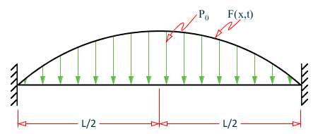
Beam with harmonic distributed load

Model: divide span 20@10.0
E = 10.0x10⁶ psi
L = 200 inches
I = 2/3 in4
A = 2 in2
Po = 0.1 lbf/in3
g = 386.4 in/sec2
The DYNRE2 run utilizes all 19 modes calculated by STAAD (Steady State analysis) for which a value of 1.0(10)-10 times critical damping is assigned. A single forcing frequency equal to 7.5 Hz is specified for the distributed load. This load is distributed to the nodes by calculating the total integrated load for each beam and lumping one-half of this force to the respective i and j nodes.
Theoretical Solution
- Blevins, R. D., "Formulas for natural Frequency and Mode Shape," Van Nostrand Reinhold, 1979, pp 108, 455-486.
- Warburton, G. B., "The Dynamical Behavior of Structures," Pergamon Press, 1964, pp. 10-15, 85, 86.
The natural frequencies of the system are calculated using the equations from reference 1 page 108 and reference 2 page 85.
where| = | ||
| = | = 4.5156271*10-1λi 2 |
λisatisfies the characteristic equation:
cosλ coshλ - 1 = 0
| i | λi | ωi | fi |
|---|---|---|---|
| 1 | 4.730041 | 63.47865 | 10.10294 |
| 2 | 7.853205 | 174.9814 | 27.84915 |
| 3 | 10.99561 | 343.0334 | 54.59546 |
| 4 | 14.13717 | 567.0517 | 90.24907 |
| 5 | 17.27876 | 847.0773 | 134.8165 |
| 6 | 20.42035 | 1183.108 | 188.2975 |
| 7 | 23.56194 | 1575.144 | 250.6919 |
| 8 | 26.70354 | 2023.185 | 321.9998 |
The mode shapes are:
Where:
The response of mode i to a harmonic force:
Where ψi is the response phase lag relative to the applied force and c is the damping.
Since c = 0.0, ψi = 0.0
Upon substitution and rearranging terms:
From reference 1, page 466, case c and page 467, case 29:
Since the load is symmetric, this expression is zero for I = 2, 4, 6 …;
Therefore, i = 1,3,5……, and: (-1)i = -1
And from the reference, βi = λi/l
So:
From Reference 1, page 457 case 5:
Therefore:
ω = 7.5(2π) = 47.1239 radians/sec
| i | λi | ωi | ηi(t) | σi | φ(1/4) | φ(1/2) |
|---|---|---|---|---|---|---|
| 1 | 4.730041 | 63.47865 | 0.9825022 | 0.8631319 | 1.5881463 | |
| 3 | 10.99561 | 343.0334 | 0.9999664 | 1.3708047 | -1.4059984 | |
| 5 | 17.27876 | 847.0773 | 0.9999999 | -0.5278897 | 1.4145675 | |
| 7 | 23.56194 | 1575.144 | 1.0000000 | -1.3037973 | -1.4141982 |
| i | φ(1/4)ηi(t) | φ(1/2)ηi(t) |
|---|---|---|
| 1 | -0.6592727 | -1.2130493 |
| 3 | -0.0030357 | 0.0031137 |
| 5 | 0.0000764 | -0.0002048 |
| 7 | 0.0000293 | -0.0000318 |
| Summation | -0.6622028 | -1.2101086 |
Comparison
| Location | Theory | STAAD Advanced Analysis |
|---|---|---|
| Node 6 (X = 50 inches) | 0.66220 | 0.65963 |
| Node 11 (X = 100 inches) | 1.21011 | 1.20545 |
Steady-state analysis requires the STAAD.Pro Advanced Analysis Plus license.
STAAD Input
The file C:\Users\Public\Public Documents\STAAD.Pro CONNECT Edition\Samples\ Verification Models\08 Dynamic Analysis\Steady State Loading on a Beam.STD is included in the STAAD.Pro installation folder.
STAAD SPACE
START JOB INFORMATION
ENGINEER DATE 29-Mar-06
END JOB INFORMATION
* FIXED BEAM SUBJECTED TO A HARMONIC LOAD WITH A PARABOLIC DISTRIBUTION X
*                    NUMBER OF NODES             21                     X
*                    HIGH NODE NUMBER            21                     X
*                    NODES FULLY RESTRAINED       2                     X
*                    NUMBER OF BEAM ELEMENTS     20                     X
*                    NUMBER OF EIGENVECTORS      19
SET SHEAR
UNIT INCHES POUND
JOINT COORDINATES
1 0 0 0; 2 10 0 0; 3 20 0 0; 4 30 0 0; 5 40 0 0; 6 50 0 0; 7 60 0 0;
8 70 0 0; 9 80 0 0; 10 90 0 0; 11 100 0 0; 12 110 0 0; 13 120 0 0;
14 130 0 0; 15 140 0 0; 16 150 0 0; 17 160 0 0; 18 170 0 0; 19 180 0 0;
20 190 0 0; 21 200 0 0;
MEMBER INCIDENCES
1 1 2; 2 2 3; 3 3 4; 4 4 5; 5 5 6; 6 6 7; 7 7 8; 8 8 9; 9 9 10;
10 10 11; 11 11 12; 12 12 13; 13 13 14; 14 14 15; 15 15 16; 16 16 17;
17 17 18; 18 18 19; 19 19 20; 20 20 21;
MEMBER PROPERTY AMERICAN
1 TO 20 PRIS AX 2 AY 0 AZ 0 IX 0.001 IY 0.666667 IZ 0.166667
SUPPORTS
2 TO 20 FIXED BUT FY MZ
1 21 FIXED
DEFINE MATERIAL START
ISOTROPIC MATERIAL1
E 1e+07
POISSON 0.3
DENSITY 0.0999194
END DEFINE MATERIAL
CONSTANTS
BETA 90 ALL
MATERIAL MATERIAL1 ALL
CUT OFF MODE SHAPE 7
CUT OFF FREQUENCY 500
LOAD 1
SELFWEIGHT X 1
SELFWEIGHT Y 1
SELFWEIGHT Z 1
MODAL CALCULATION REQUESTED
PERFORM STEADY STATE ANALYSIS
BEGIN STEADY FORCE
STEADY FORCE FREQ 7.5 DAMP 1e-10
JOINT LOAD
2 FY 1.8666
3 FY 3.5666
4 FY 5.0666
5 FY 6.3666
6 FY 7.4666
7 FY 8.3666
8 FY 9.0666
9 FY 9.5666
10 FY 9.8666
11 FY 9.9666
12 FY 9.8666
13 FY 9.5666
14 FY 9.0666
15 FY 8.3666
16 FY 7.4666
17 FY 6.3666
18 FY 5.0666
19 FY 3.5666
20 FY 1.8666
END
PRINT JOINT DISPLACEMENTS LIST 6 11
FINISH
STAAD Output
            P R O B L E M   S T A T I S T I C S
            -----------------------------------
     NUMBER OF JOINTS         21  NUMBER OF MEMBERS      20
     NUMBER OF PLATES          0  NUMBER OF SOLIDS        0
     NUMBER OF SURFACES        0  NUMBER OF SUPPORTS     21
           Using 64-bit analysis engine.
           SOLVER USED IS THE IN-CORE ADVANCED MATH SOLVER
   TOTAL      PRIMARY LOAD CASES =     1, TOTAL DEGREES OF FREEDOM =      38
   TOTAL LOAD COMBINATION  CASES =     0  SO FAR.
   ***NOTE: MASSES DEFINED UNDER LOAD#       1 WILL FORM
            THE FINAL MASS MATRIX FOR DYNAMIC ANALYSIS.
 EIGEN METHOD   : SUBSPACE
 -------------------------
 NUMBER OF MODES REQUESTED              =     7
 NUMBER OF EXISTING MASSES IN THE MODEL =    19
 NUMBER OF MODES THAT WILL BE USED      =     7
   ***  EIGENSOLUTION : ADVANCED METHOD ***
      STAAD SPACE                                              -- PAGE NO.    3
               CALCULATED FREQUENCIES FOR LOAD CASE       1
       MODE            FREQUENCY(CYCLES/SEC)         PERIOD(SEC)
         1                      10.103                  0.09898
         2                      27.849                  0.03591
         3                      54.591                  0.01832
         4                      90.230                  0.01108
         5                     134.747                  0.00742
         6                     188.093                  0.00532
         7                     250.166                  0.00400
            MODAL WEIGHT (MODAL MASS TIMES g) IN POUN         GENERALIZED
      MODE           X             Y             Z              WEIGHT
         1       0.000000E+00  2.759074E+01  0.000000E+00    1.584634E+01
         2       0.000000E+00  1.241542E-21  0.000000E+00    1.763389E+01
         3       0.000000E+00  5.287477E+00  0.000000E+00    1.757978E+01
         4       0.000000E+00  5.783031E-23  0.000000E+00    1.788088E+01
         5       0.000000E+00  2.138447E+00  0.000000E+00    1.901368E+01
         6       0.000000E+00  1.058584E-19  0.000000E+00    1.837854E+01
         7       0.000000E+00  1.145139E+00  0.000000E+00    1.756698E+01
 MASS PARTICIPATION FACTORS
                     MASS  PARTICIPATION FACTORS IN PERCENT
                     --------------------------------------
           MODE    X     Y     Z     SUMM-X   SUMM-Y   SUMM-Z
             1     0.00  72.67   0.00    0.000   72.666    0.000
             2     0.00   0.00   0.00    0.000   72.666    0.000
             3     0.00  13.93   0.00    0.000   86.591    0.000
             4     0.00   0.00   0.00    0.000   86.591    0.000
             5     0.00   5.63   0.00    0.000   92.223    0.000
             6     0.00   0.00   0.00    0.000   92.223    0.000
             7     0.00   3.02   0.00    0.000   95.239    0.000
    44. BEGIN STEADY FORCE
    45. STEADY FORCE FREQ 7.5 DAMP 1E-10
    46. JOINT LOAD
      STAAD SPACE                                              -- PAGE NO.    4
    47. 2 FY 1.8666
    48. 3 FY 3.5666
    49. 4 FY 5.0666
    50. 5 FY 6.3666
    51. 6 FY 7.4666
    52. 7 FY 8.3666
    53. 8 FY 9.0666
    54. 9 FY 9.5666
    55. 10 FY 9.8666
    56. 11 FY 9.9666
    57. 12 FY 9.8666
    58. 13 FY 9.5666
    59. 14 FY 9.0666
    60. 15 FY 8.3666
    61. 16 FY 7.4666
    62. 17 FY 6.3666
    63. 18 FY 5.0666
    64. 19 FY 3.5666
    65. 20 FY 1.8666
    66. END
*DIRECTIONS FOR WHICH AMPLITUDE VS. FREQUENCY DATA WAS ENTERED =    0   2   0   0   0   0
*DIRECTIONS FOR WHICH AMPLITUDE VS. PHASE LAG DATA WAS ENTERED =    0   0   0   0   0   0
               FORCE  DIRECTION NUMBER    2
              FREQUENCY      AMPLITUDE      PHASE ANGLE
         1   0.749800E+01   0.100000E+01   0.000000E+00
         2   0.750200E+01   0.100000E+01   0.000000E+00
      STAAD SPACE                                              -- PAGE NO.    5
                         7 MODES (EIGENVECTORS) HAVE BEEN SELECTED.
 MODE       NATURAL FREQUENCY          GENERALIZED WEIGHT        DAMPING    DAMPED FREQUENCY
 NO.       (HZ)        (RAD/SEC)     (WEIGHT)       (MASS)     COEFFICIENT       (HZ)
    1  1.010292E+01  6.347852E+01  1.584634E+01  4.104327E-02  1.000000E-10  1.010292E+01
    2  2.784865E+01  1.749782E+02  1.763389E+01  4.567317E-02  1.000000E-10  2.784865E+01
    3  5.459144E+01  3.430081E+02  1.757978E+01  4.553302E-02  1.000000E-10  5.459144E+01
    4  9.022966E+01  5.669297E+02  1.788088E+01  4.631289E-02  1.000000E-10  9.022966E+01
    5  1.347470E+02  8.466405E+02  1.901368E+01  4.924693E-02  1.000000E-10  1.347470E+02
    6  1.880927E+02  1.181821E+03  1.837854E+01  4.760188E-02  1.000000E-10  1.880927E+02
    7  2.501660E+02  1.571839E+03  1.756698E+01  4.549988E-02  1.000000E-10  2.501660E+02
                     PARTICIPATION FACTORS FOR EACH MODE
   MODE NO.       X             Y             Z             MX            MY            MZ
         1  0.000000E+00  0.218577E+04  0.000000E+00  0.000000E+00  0.000000E+00  0.000000E+00
         2  0.000000E+00 -0.139214E-07  0.000000E+00  0.000000E+00  0.000000E+00  0.000000E+00
         3  0.000000E+00  0.382113E+03  0.000000E+00  0.000000E+00  0.000000E+00  0.000000E+00
         4  0.000000E+00 -0.416926E-08  0.000000E+00  0.000000E+00  0.000000E+00  0.000000E+00
         5  0.000000E+00 -0.148269E+03  0.000000E+00  0.000000E+00  0.000000E+00  0.000000E+00
         6  0.000000E+00  0.128546E-06  0.000000E+00  0.000000E+00  0.000000E+00  0.000000E+00
         7  0.000000E+00 -0.829074E+02  0.000000E+00  0.000000E+00  0.000000E+00  0.000000E+00
    67. PRINT JOINT DISPLACEMENTS LIST 6 11
  JOINT    DISPLACE LIST     6
      STAAD SPACE                                              -- PAGE NO.    6
   JOINT DISPLACEMENT (INCH RADIANS)    STRUCTURE TYPE = SPACE
   ------------------
 JOINT  LOAD   X-TRANS   Y-TRANS   Z-TRANS   X-ROTAN   Y-ROTAN   Z-ROTAN
      6    1    0.00000   0.65963   0.00000   0.00000   0.00000   0.01831
     11    1    0.00000   1.20545   0.00000   0.00000   0.00000   0.00000
   ************** END OF LATEST ANALYSIS RESULT **************