EX. To design the brace gusset plate connection
So far, you have selected members which form a joint for design. In this procedure, you will use some of the quick selection tools in the program which can be used to select all joints of a similar type.
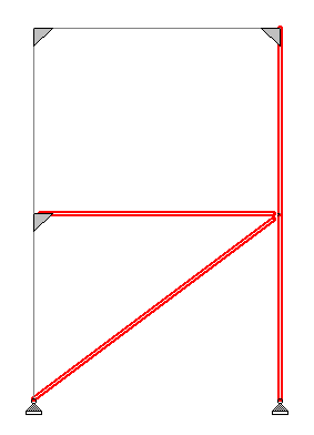
- On the Connection Design ribbon tab, select the tool in the Assign Connections group. Members 1, 2, 4, 5, and 7 are selected.
- Hold <Ctrl> and then click the lower, left column section to remove it from the selection set. The lower end of the brace ends at a support so a separate connection design incorporating the base plate is needed.
-
On the
Connection Design ribbon tab, select the
Gusset Connections tool in the
Assign Connections group.

The Gusset Connections dialog opens. - Select AISC 360-10 (ASD) as the Design Code. Leave all other options unchecked.
- Select Gusset Plate CBB (Gusset Plate, Column-Beam-Brace) from the connection types drop-down list.
- Double-click the CBB_DW_CBF entry in the Available list. This is a Column-Beam-Brace connection, directly welded, at the column and beam flanges. It is added to the Selected list.
- Click OK. The RAM Connection - Validation dialog opens to display the design results overview.
- Click Close. The connection design is added to the RAM Connection Input table.