T.3 Specifying Primary Load Cases
Three primary load cases are required for this structure.
The STAAD input file commands generated are:
UNIT METER KG
LOAD 1 DEAD LOAD
SELF Y -1.0
LOAD 2 EXTERNAL PRESSURE LOAD
ELEMENT LOAD
1 TO 6 PR GY -300
LOAD 3
TEMPERATURE LOAD
1 TO 6 TEMP 40 30-
Change the units:
Note: The pressure load value listed in the beginning of this tutorial is in KN and meter units. Rather than convert that value to the current input units, this tutorial will conform to those units. The current input units, which you last set by specifying the thickness was centimeter. Therefore, you need to change the force unit to Kilogram and the length units to Meter.
-
Add the dead load case:
-
On the
Loading ribbon tab, select the
Primary Load Case tool in the
Loading Specifications group.

-
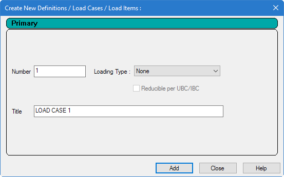
Type
Dead Load as the
Title for Load Case 1.
Leave the Number as the default (1) and leave the Loading Type as None.
Note: The Loading Type list is used to associate the load case we are creating with any of the ACI, AISC, IBC, or other code-prescribed definitions of Dead, Live, Ice, etc. This type of association needs to be done if you intend to use the program's automatically generating load combinations in accordance with those codes. Note that there is a check box labeled Reducible per UBC/IBC. This feature is active only when the load case is assigned a Loading Type called Live when you create that load case. - Click Add.
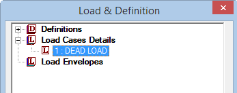
The newly created load case will now appear under the Load Cases Details in the Load & Definition dialog.
-
On the
Loading ribbon tab, select the
Primary Load Case tool in the
Loading Specifications group.
-
Create the selfweight load:
-
On the
Loading ribbon tab, select the
Load Items tool in the
Loading Specifications group.

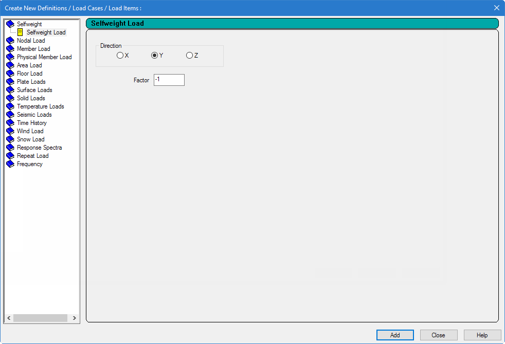
The Add New Load Items dialog opens.
- Select the Selfweight Load option under the Selfweight item.
- Select the Direction as Y
-
Type the
Factor as
-1.0.
The negative number signifies that the selfweight load acts opposite to the positive direction of the global axis (Y in this case) along which it is applied.
- Click Add.
-
On the
Loading ribbon tab, select the
Load Items tool in the
Loading Specifications group.
- Assign the selfweight load to all of the elements:
-
Add the pressure load case:
-
On the
Loading ribbon tab, select the
Primary Load Case tool in the
Loading Specifications group.
The Add New Load Cases dialog opens.
-
Type
External Pressure Load as the
Title.
Again, there is no need to associate the load case with any code based Loading Type so leave the selection as None.
- Click Add.
-
On the
Loading ribbon tab, select the
Primary Load Case tool in the
Loading Specifications group.
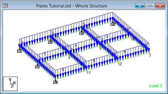
- On the Loading ribbon tab Display group, select 2: External Pressure Load from the Load drop-down list.
-
Create the pressure load:
-
On the
Loading ribbon tab, select the
Load Items tool in the
Loading Specifications group.
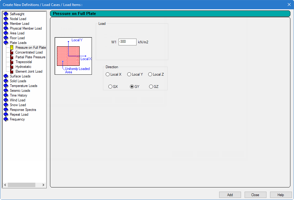
The Add New Load Items dialog opens. -
Select the
Pressure on Full Plate option under the
Plate Loads item.
This type enables the load to be applied on the full area of the element.
Note: The Concentrated Load is for applying a concentrated force on the element. The Trapezoidal and Hydrostatic options are for defining pressures with intensities varying from one point to another. The Partial Plate Pressure Load is useful if the load is to be applied as a "patch" on a small localized portion of an element. - Type -300 kg/m2 in the W1 field (force)
- Select GY as the Direction (global Y direction).
- Click Add.
- Click Close.
-
On the
Loading ribbon tab, select the
Load Items tool in the
Loading Specifications group.
- Repeat steps 5 and 6 to create a third load case titled Temperature Load and then select it on the Loading ribbon tab Display group.
-
To generate and assign the third load type:
-
On the
Loading ribbon tab, select the
Load Items tool in the
Loading Specifications group.
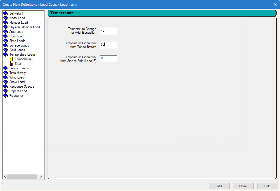
The Add New Load Items dialog opens. - Select the Temperature option under the Temperature Loads item.
- Type 40 in the Temperature Change for Axial Elongationfield.
-
Type
30 in the
Temperature Differential from Top to
Bottom field.
Leave the Temperature Differential from Side to Side (Local Z) field as 0 (default).
- Click Add and then click Close.
-
On the
Loading ribbon tab, select the
Load Items tool in the
Loading Specifications group.
- To apply the pressure load and temperature load on all the plates, repeat step 4 for each load item.