V. IS 800 2007 LSD - I Section with Cover Plate
Verify the design of an I section with cover plates subject to axial force and biaxial bending per the IS 800:2007 limit state method.
BIS. IS 800: General Construction in Steel - Code of Practice. 2007. Bureau of Indian Standards. New Delhi.
BIS. IS 808: Dimensions for Hot Rolled Steel Beam, Column, Channel and Angle Sections. 1989. Bureau of Indian Standards. New Delhi.
Details
- a 55.98 kN·m moment about the major axis
- a 10 kN·m moment about the minor axis
- a 23.984 kN compressive force
- a 2 kN shear force along the major axis
- a 1.2 kN shear force along the minor axis
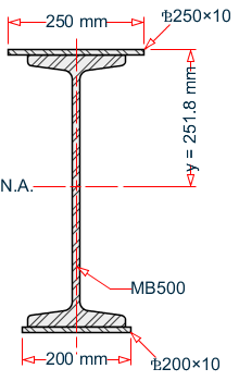
The section used is an ISMB500 with a 250 mm × 10 mm top cover plate and a 200 mm × 10 mm bottom cover plate. The section is braced to prevent lateral-torsional buckling. The steel has a yield strength of 250 MPa, an ultimate tensile strength of 420 MPa, and a modulus of elasticity of 205×(10)3 MPa.
Validation
Section Properties
Overall depth of the whole section, h = D + tpl1 + tpl2 = 500 + 10 + 10 = 520 mm
Depth of web of IS MB500, dw = D - 2×tf = 500 - 2 × 17.2 = 465.6 mm
Cross-section area of top cover plate, Atop = 25 cm × 1 cm = 25 cm2
Cross-section area of bottom cover plate, Abottom = 20 cm × 1 cm = 20 cm2
Cross-section area, Ax = 111 cm2 + 25 cm2 + 20 cm2 = 156 cm2
Distance of CG from top of overall section:
Overall moment of inertia about the major axis:
Overall moment of inertia about the minor axis (section is symmetric about this axis):
Radius of gyration about the major axis,
Radius of gyration about the minor axis,
Elastic section modulus about the major axis,
Elastic section modulus about the minor axis,
Distance to equal area axis from top,
Plastic section modulus about the major axis,
Plastic section modulus about the minor axis,
Constants
- γm0 = 1.1
- γm1 = 1.25
Section Classification
Section classification of different portions of the section must be checked separately. Checking is performed per Table 2 of IS 800:2007 as indicated in the following figure:
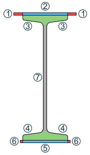
- Outstanding element of top cover plate: hence, plastic.
- Internal element of top cover plate: hence, plastic.
- Internal element of top flange hence, plastic.
- Internal element of bottom flange hence, plastic.
- Internal element of bottom cover plate hence, plastic.
- Outstanding element of bottom cover plate hence, plastic.
- Web of ISMB section hence, plastic.
Overall classification of the section is based on the most critical class among the different classes identified above. Here, the overall section is classified as "plastic".
Since tf = 17.2 mm < 40 mm
Hence, from Table 10, as per the requirements of welded I section, the buckling class about major axis buckling is "b" and the same about minor axis buckling is "c".
Check Slenderness Ratio
ky = kz = 1
The maximum allowable slenderness ratio is 180.
Slenderness ratio about the major axis, kzL / rz = 1.0 × 500 / 21.8 = 22.9 < 180
Slenderness ratio about the minor axis, kyL / ry = 1.0 × 500 / 4.63 = 108.0 < 180
So the slenderness is within the limit.
Axial Tension Capacity
Check for yielding of gross section:
Tdg = Ag × fy / γm0 = 3,545 kN
Check for rupture of critical section:
α = 0.8
Tdn = α × Anet × fu / γm1 = 4,193 kN
Block shear areas are not specified and therefore not checked.
No tension in the member, so critical ratio is 0.
Check Axial Compression
Axial compression capacity of major axis:
The non-dimensional slenderness ratio,
For buckling class "b", the imperfection factor, α = 0.34
So, as per Cl. 7.1.2.1 of IS 800:2007,
Therefore, axial compression capacity in the major axis: Pdz = Axfcdz = 3,477 kN
Axial compression capacity of minor axis:
The non-dimensional slenderness ratio,
For buckling class "c", the imperfection factor, α = 0.49
So, as per Cl. 7.1.2.1 of IS 800:2007,
Therefore, axial compression capacity in the minor axis: Pdy = Axfcdy = 1,536 kN, which governs.
The critical ratio for axial compression in minor axis = 23.98 / 1,536 = 0.007
Check Shear Capacity
Major Axis
As per Cl. 8.4.1.1 of IS 800:2007, the shear area, Avz = 2×bftf + bp1tp1 + bp2tp2 = 10,692 mm2
So, as per Cl. 8.4.1,
Hence, shear capacity along major axis:
Minor Axis
As per Cl. 8.4.1.1 of IS 800:2007, the shear area, Avy = dw×tw = 4,749 mm2
So, as per Cl. 8.4.1,
Hence, shear capacity along major axis:
As per Cl. 8.4.2, dw / tw = 45.65 < 67ε, so resistance to shear buckling need not be checked.
Shear force along major axis = 2 kN.
Critical shear ratio along major axis: 2 / 1,403 = 0.001
Shear force along minor axis = 1.2 kN.
Critical shear ratio along minor axis: 1.2 / 623.2 = 0.002
Check Bending Capacity
Since the section has been classified as "plastic", βb = 1.
The section is low shear in both axes.
Major Axis Bending
Actual bending moment about the major axis is Mz = 55.98 kN·m.
The critical bending ratio in the major axis is 55.98 / 724.9 = 0.077
Minor Axis Bending
Actual bending moment about the minor axis is Mz = 10 kN·m.
The critical bending ratio in the minor axis is 10 / 124.3 = 0.080
Check Combined Interaction of Axial Compression and Bending
Section strength calculation as per Cl. 9.3.1:
n = N / Nd = 0.007 < 0.2
Hence, from Table 17:
α1 = max(5n , 1) = 1
α2 = 2
As per 9.3.1.2(b),
n1 = max(n,a) = 0.603
Therefore:
Overall member strength in bending and axial compression
ny = Fx / Pdy = 0.016
nz = Fx / Pdz = 0.007
Results
| Result Type | Reference | STAAD.Pro | Difference | Comments |
|---|---|---|---|---|
| Slenderness ratio | 108.0 | 108.08 | negligible | |
| Tension capacity, gross yielding (kN) | 3,545 | 3,545 | none | |
| Tension capacity, rupture of critical section (kN) | 4,193 | 4,163 | negligible | |
| Axial compression capacity about major axis (kN) | 3,477 | 3,477 | none | |
| Axial compression capacity about minor axis (kN) | 1,536 | 1,536 | none | |
| Critical ratio for axial compression | 0.016 | 0.016 | none | |
| Shear capacity in major axis (kN) | 1,403 | 1,403 | none | |
| Shear capacity in minor axis (kN) | 623.2 | 623.16 | negligible | |
| Ratio for shear in major axis | 0.001 | 0.001 | none | |
| Ratio for shear in minor axis | 0.002 | 0.002 | none | |
| Bending capacity about major axis (kN·m) | 724.9 | 724.745 | negligible | |
| Bending capacity about minor axis (kN·m) | 124.3 | 124.317 | negligible | |
| Ratio for bending about major axis | 0.077 | 0.077 | none | |
| Ratio for bending about minor axis | 0.080 | 0.080 | none | |
| Ratio per Cl. 9.3.1.1 | 0.086 | 0.086 | none | |
| Ratio per Eq.2 of Cl. 9.3.2.2 | 0.120 | 0.120 | none |
STAAD.Pro Input
The file C:\Users\Public\Public Documents\STAAD.Pro CONNECT Edition\Samples\ Verification Models\09 Steel Design\India\IS 800 2007 LSD - I Section with Cover Plate.std is typically installed with the program.
The following design parameters are used:
- The default value of ALPHA is used.
- The default values of KY and KZ are used.
- The default value of the maximum allowable slenderness ratio, MAIN, of 180 is used.
- The beam type is a general member, specified by CAN 0
- The beam is laterally supported, specified by LAT 1
- The default values of CMX, CMY, and CMZ of 0.9 are used.
STAAD SPACE
START JOB INFORMATION
ENGINEER DATE 22-Oct-08
END JOB INFORMATION
INPUT WIDTH 79
*******************************************************************************
*THIS EXAMPLE DEMONSTRATES THE DESIGN OF A WIDE FLANGE SECTION WITH
*ADDITIONAL TOP AND BOTTOM COVER PLATES USING PROVISIONS OF IS 800:2007 LSD
*******************************************************************************
SET SHEAR
UNIT METER KN
JOINT COORDINATES
1 0 0 0; 2 0 5 0; 3 5 5 0;
MEMBER INCIDENCES
1 1 2; 2 2 3;
DEFINE MATERIAL START
ISOTROPIC STEEL
E 2.05e+008
POISSON 0.3
DENSITY 76.8195
ALPHA 1.2e-005
DAMP 0.03
END DEFINE MATERIAL
MEMBER PROPERTY INDIAN
1 2 TABLE TB ISMB500 WP 0.25 TH 0.01 BW 0.2 BT 0.01
CONSTANTS
MATERIAL STEEL ALL
SUPPORTS
1 FIXED
LOAD 1 LOADTYPE None  TITLE LOAD CASE 1
JOINT LOAD
3 FY -2
MEMBER LOAD
2 UNI GY -2
JOINT LOAD
2 FX 1.2
2 FZ -2
SELFWEIGHT Y -1 LIST ALL
PERFORM ANALYSIS
PRINT SUPPORT REACTION
PRINT MEMBER FORCES
PARAMETER 1
CODE IS800 LSD
CAN 0 MEMB 1
LAT 1 ALL
TRACK 2 MEMB 1
CHECK CODE MEMB 1
FINISH
STAAD.Pro Output
                       STAAD.PRO CODE CHECKING - IS-800-2007-LSD (V2.2)
                     ****************************************************
 |----------------------------------------------------------------------------------|
 |   Member Number:      1                                                          |
 |  Member Section:  TB   ISMB500               (INDIAN SECTIONS)                   |
 |  Status: PASS  Ratio:   0.600  Critical Load Case:     1  Location:       0.00   |
 |  Critical Condition: Slenderness (Compression)                                   |
 |  Critical Design Forces:  (Unit: KN    METE)                                     |
 |      FX:      23.984E+00 C     FY:       1.200E+00      FZ:       2.000E+00      |
 |      MX:       0.000E+00       MY:     -10.000E+00      MZ:      55.980E+00      |
 |----------------------------------------------------------------------------------|
 |  Section Properties:    (Unit:  CM  )                                            |
 |  AXX:     156.000E+00          IZZ:      74.381E+03          RZZ:      21.836E+00|
 |  AYY:      47.491E+00          IYY:       3.339E+03          RYY:       4.626E+00|
 |  AZZ:     106.920E+00          IXX:     117.000E+00           CW:       2.057E+06|
 |  ZEZ:       2.773E+03          ZPZ:       3.189E+03                              |
 |  ZEY:     267.100E+00          ZPY:     547.000E+00                              |
 |----------------------------------------------------------------------------------|
 |  Slenderness Check:    (Unit:  KN    METE)                                       |
 |  Actual Length:        5.000E+00                                                 |
 |  Parameters:     LZ:        5.000E+00  LY:        5.000E+00                      |
 |                  KZ:            1.000  KY:            1.000                      |
 |  Actual Ratio: 108.08 Allowable Ratio: 180.00  LOAD:     1                       |
 |----------------------------------------------------------------------------------|
 |  Section Class:      Plastic; Flange Class:      Plastic; Web Class:      Plastic|
 |----------------------------------------------------------------------------------|
      STAAD SPACE                                              -- PAGE NO.    6
                       STAAD.PRO CODE CHECKING - IS-800-2007-LSD (V2.2)
                     ****************************************************
 |----------------------------------------------------------------------------------|
 |  Member Number:      1                                                           |
 |  Member Section:  TB   ISMB500               (INDIAN SECTIONS)                   |
 |----------------------------------------------------------------------------------|
 |  Tension:    (Unit:  KN    METE)                                                 |
 |  Parameters:     FYLD:      250.000E+03       FU:      420.000E+03               |
 |                   NSF:            1.000    ALPHA:            0.800               |
 |  Yielding   :  Design Force:        0.000E+00     LC:     0                      |
 |                Capacity:            3.545E+03     As per:  Sec. 6.2              |
 |  Rupture    :  Design Force:        0.000E+00     LC:     0                      |
 |                Capacity:            4.193E+03     As per:  Sec. 6.3              |
 |----------------------------------------------------------------------------------|
 |  Compression:    (Unit:  KN    METE)                                             |
 |  Buckling Class:   Major: b    Minor: c    As per:Cl. 7.1.2.2                    |
 |  Major Axis:   Design Force:       23.984E+00    LC:     1  Loc:     0.000       |
 |                Capacity:            3.477E+03    As per:  Sec. 7.1.2             |
 |  Minor Axis:   Design Force:       23.984E+00    LC:     1  Loc:     0.000       |
 |                Capacity:            1.536E+03    As per:  Sec. 7.1.2             |
 |----------------------------------------------------------------------------------|
 |  Shear:    (Unit:  KN  )                                                         |
 |  Major Axis:   Design Force:        2.000E+00    LC:     1  Loc:     0.000       |
 |                Capacity:            1.403E+03    As per:  Sec. 8.4               |
 |  Minor Axis:   Design Force:        1.200E+00    LC:     1  Loc:     0.000       |
 |                Capacity:          623.160E+00    As per:  Sec. 8.4               |
 |----------------------------------------------------------------------------------|
 |  Bending:    (Unit:  KN    METE)                                                 |
 |  Parameters:   Laterally Supported      KX:   1.00  LX:   5.000E+00  General     |
 |  Major Axis:   Design Force:       55.980E+00    LC:     1  Loc:     0.000       |
 |                Capacity:          724.754E+00    As per:  Sec. 8.2.1.2           |
 |  Minor Axis:   Design Force:      -10.000E+00    LC:     1  Loc:     0.000       |
 |                Capacity:          124.318E+00    As per:  Sec. 8.2.1.2           |
 |----------------------------------------------------------------------------------|
 |  Combined Interaction:                                                           |
 |  Parameters:  PSI: 1.00   CMX:    0.900   CMY:    0.900   CMZ:    0.900          |
 |  Section Strength:    Ratio:     0.086    As per:  Sec. 9.3.1.1                  |
 |                       LC:            1    Loc:       0.000                       |
 |  Overall Member Strength (Bending+Compression):                                  |
 |  Equation 2:          Ratio:     0.120    As per:  Sec. 9.3.2.2   Ky :   1.0125  |
 |                       LC:            1    Loc:       0.000        Kz :   1.0004  |
 |----------------------------------------------------------------------------------|
 |  Checks               Ratio   Load Case No.      Location from Start( METE)      |
 |                                                                                  |
 |  Tension                0.000       0                       0.000E+00            |
 |  Compression            0.016       1                       0.000E+00            |
 |  Shear Major            0.001       1                       0.000E+00            |
 |  Shear Minor            0.002       1                       0.000E+00            |
 |  Bend Major             0.077       1                       0.000E+00            |
 |  Bend Minor             0.080       1                       0.000E+00            |
 |  Sec. 9.3.1.1           0.086       1                       0.000E+00            |
 |  Sec. 9.3.2.2(ii)       0.120       1                       0.000E+00            |
 |----------------------------------------------------------------------------------|