V. Forces on a Propped Cantilever 1
To find the deflection and member forces due to an applied load on a propped cantilever beam with a compression only support.
Reference
Hand calculation using the following reference:
Manual of Steel Construction, Load and Resistance Factor Design, Second Edition, American Institute of Steel Construction, 1998, pp. 4-194, 4-197.
Problem
- P = +0.5 lbs (up), and
- P = -0.5 lbs (down)
-
E = 10(10)6
-
width = 0.6 in
-
depth = 0.3 in
-
L = 4 ft
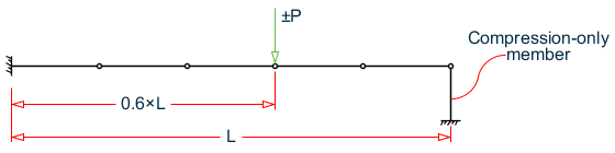
Propped cantilever member with a compression only support
Load Case 1
General solution equations found on p.2-121 of the reference. In this case, the "propped" end carries no load as the support cannot carry tension. Thus, the member acts like a pure cantilever.
At the rigid support, M = 14.4 in·lb.
By inspection, fixed end shear is equal to load value = 0.50 lb.
Comparison
| Load Case | Result Type | Theory | STAAD.Pro | Difference |
|---|---|---|---|---|
| LC 1 | Moment at fixed end (in·lb) | -14.4 | -14.4 | none |
| Shear at fixed end (lb) | 0.50 | 0.50 | none | |
| Deflection at load (.in) | 0.295 | 0.295 | none | |
| LC 2 | Moment at fixed end (in·lb) | 4.032 | 4.03 | none |
| Shear at fixed end (lb) | 0.284 | 0.28 | 1.4% | |
| Deflection at load (.in) | -0.040 | -.0401 | none |
STAAD Input
The file C:\Users\Public\Public Documents\STAAD.Pro CONNECT Edition\Samples\ Verification Models\01 Beams\Forces on a Propped Cantilever 1.STDis typically installed with the program.
STAAD PLANE :A PROPPED CANTILEVER WITH COMPRESSION ONLY SUPPORT
START JOB INFORMATION
ENGINEER DATE 18-Sep-18
END JOB INFORMATION
*********************************************
* The end support is to be defined as a     *
* compression only support.  A dummy member,*
* #7, is set as compression only to model   *
* this.                                     *
*********************************************
SET NL 2
UNIT INCHES POUND
JOINT COORDINATES
1 0 0 0; 2 9.6 0 0; 3 19.2 0 0; 4 28.8 0 0; 5 38.4 0 0; 6 48 0 0;
7 48 -4 0;
MEMBER INCIDENCES
1 1 2; 2 2 3; 3 3 4; 4 4 5; 5 5 6; 6 6 7;
MEMBER PROPERTY AMERICAN
1 TO 5 PRIS YD 0.3 ZD 0.6
6 PRIS YD 40
MEMBER COMPRESSION
6
DEFINE MATERIAL START
ISOTROPIC MATERIAL1
E 1e+07
POISSON 0.33
END DEFINE MATERIAL
CONSTANTS
MATERIAL MATERIAL1 ALL
SUPPORTS
1 FIXED
7 FIXED
*7 PINNED
LOAD 1 UPWARD
JOINT LOAD
4 FY 0.5
PERFORM ANALYSIS
PRINT MEMBER FORCES LIST 1 TO 5
PRINT JOINT DISPLACEMENTS LIST 1 TO 6
PRINT SUPPORT REACTION
CHANGE
LOAD 2 DOWNWARD
JOINT LOAD
4 FY -0.5
PERFORM ANALYSIS
PRINT SUPPORT REACTION
PRINT MEMBER FORCES LIST 1 TO 5
PRINT JOINT DISPLACEMENTS LIST 1 TO 6
FINISH
STAAD Output
   ALL UNITS ARE -- POUN INCH     (LOCAL )
  MEMBER  LOAD  JT     AXIAL   SHEAR-Y  SHEAR-Z   TORSION     MOM-Y      MOM-Z
      1    1     1      0.00     -0.50     0.00      0.00      0.00     -14.40
                 2      0.00      0.50     0.00      0.00      0.00       9.60
      2    1     2      0.00     -0.50     0.00      0.00      0.00      -9.60
                 3      0.00      0.50     0.00      0.00      0.00       4.80
      3    1     3      0.00     -0.50     0.00      0.00      0.00      -4.80
                 4      0.00      0.50     0.00      0.00      0.00       0.00
      4    1     4      0.00     -0.00     0.00      0.00      0.00      -0.00
                 5      0.00      0.00     0.00      0.00      0.00       0.00
      5    1     5      0.00      0.00     0.00      0.00      0.00       0.00
                 6      0.00     -0.00     0.00      0.00      0.00       0.00
   ************** END OF LATEST ANALYSIS RESULT **************
    39. PRINT JOINT DISPLACEMENTS LIST 1 TO 6
  JOINT    DISPLACE LIST     1
      :A PROPPED CANTILEVER WITH COMPRESSION ONLY SUPPORT      -- PAGE NO.    4
   JOINT DISPLACEMENT (INCH RADIANS)    STRUCTURE TYPE = PLANE
   ------------------
 JOINT  LOAD   X-TRANS   Y-TRANS   Z-TRANS   X-ROTAN   Y-ROTAN   Z-ROTAN
      1    1    0.00000   0.00000   0.00000   0.00000   0.00000   0.00000
      2    1    0.00000   0.04370   0.00000   0.00000   0.00000   0.00853
      3    1    0.00000   0.15293   0.00000   0.00000   0.00000   0.01365
      4    1    0.00000   0.29494   0.00000   0.00000   0.00000   0.01536
      5    1    0.00000   0.44239   0.00000   0.00000   0.00000   0.01536
      6    1    0.00000   0.58985   0.00000   0.00000   0.00000   0.01536
   ************** END OF LATEST ANALYSIS RESULT **************
    40. PRINT SUPPORT REACTION
  SUPPORT  REACTION
      :A PROPPED CANTILEVER WITH COMPRESSION ONLY SUPPORT      -- PAGE NO.    5
   SUPPORT REACTIONS -UNIT POUN INCH    STRUCTURE TYPE = PLANE
   -----------------
 JOINT  LOAD   FORCE-X   FORCE-Y   FORCE-Z     MOM-X     MOM-Y     MOM Z
      1    1      0.00     -0.50      0.00      0.00      0.00    -14.40
      7    1      0.00      0.00      0.00      0.00      0.00      0.00
   ************** END OF LATEST ANALYSIS RESULT **************
    41. CHANGE
    42. LOAD 2 DOWNWARD
    43. JOINT LOAD
    44. 4 FY -0.5
    45. PERFORM ANALYSIS
  **NOTE-Tension/Compression converged after  1 iterations, Case=    2
    46. PRINT SUPPORT REACTION
  SUPPORT  REACTION
      :A PROPPED CANTILEVER WITH COMPRESSION ONLY SUPPORT      -- PAGE NO.    6
   SUPPORT REACTIONS -UNIT POUN INCH    STRUCTURE TYPE = PLANE
   -----------------
 JOINT  LOAD   FORCE-X   FORCE-Y   FORCE-Z     MOM-X     MOM-Y     MOM Z
      1    2      0.00      0.28      0.00      0.00      0.00      4.03
      7    2      0.00      0.22      0.00      0.00      0.00      0.00
   ************** END OF LATEST ANALYSIS RESULT **************
    47. PRINT MEMBER FORCES LIST 1 TO 5
  MEMBER   FORCES   LIST     1
      :A PROPPED CANTILEVER WITH COMPRESSION ONLY SUPPORT      -- PAGE NO.    7
   MEMBER END FORCES    STRUCTURE TYPE = PLANE
   -----------------
   ALL UNITS ARE -- POUN INCH     (LOCAL )
  MEMBER  LOAD  JT     AXIAL   SHEAR-Y  SHEAR-Z   TORSION     MOM-Y      MOM-Z
      1    2     1      0.00      0.28     0.00      0.00      0.00       4.03
                 2      0.00     -0.28     0.00      0.00      0.00      -1.31
      2    2     2      0.00      0.28     0.00      0.00      0.00       1.31
                 3      0.00     -0.28     0.00      0.00      0.00       1.42
      3    2     3      0.00      0.28     0.00      0.00      0.00      -1.42
                 4      0.00     -0.28     0.00      0.00      0.00       4.15
      4    2     4      0.00     -0.22     0.00      0.00      0.00      -4.15
                 5      0.00      0.22     0.00      0.00      0.00       2.07
      5    2     5      0.00     -0.22     0.00      0.00      0.00      -2.07
                 6      0.00      0.22     0.00      0.00      0.00       0.00
   ************** END OF LATEST ANALYSIS RESULT **************
    48. PRINT JOINT DISPLACEMENTS LIST 1 TO 6
  JOINT    DISPLACE LIST     1
      :A PROPPED CANTILEVER WITH COMPRESSION ONLY SUPPORT      -- PAGE NO.    8
   JOINT DISPLACEMENT (INCH RADIANS)    STRUCTURE TYPE = PLANE
   ------------------
 JOINT  LOAD   X-TRANS   Y-TRANS   Z-TRANS   X-ROTAN   Y-ROTAN   Z-ROTAN
      1    2    0.00000   0.00000   0.00000   0.00000   0.00000   0.00000
      2    2    0.00000  -0.01066   0.00000   0.00000   0.00000  -0.00190
      3    2    0.00000  -0.03024   0.00000   0.00000   0.00000  -0.00186
      4    2    0.00000  -0.04012   0.00000   0.00000   0.00000   0.00012
      5    2    0.00000  -0.02714   0.00000   0.00000   0.00000   0.00233
      6    2    0.00000   0.00000   0.00000   0.00000   0.00000   0.00307