V. AASHTO 2nd Ed LRFD - Design Beam
The following compares the solution of a design performed using STAAD.Pro against a hand calculation of steel design per the AASHTO (LRFD) code.
Details
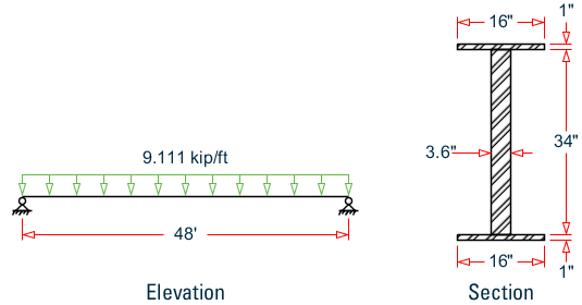
Determine the allowable resistances (AASHTO LRFD, 1998 code) for the member of the structure as shown in figure. Also, perform a code check for the member based on the results of the analysis.
A 48 foot long, non-composite girder is assumed to be simply supported. The section is a plate girder with 16" x 1" plate flanges and a 34" x 3.6" plate web (36 in. total depth). All plates are grade 36 steel.
The beam is subject to a 9.111 kip/ft uniform load.
| A = 154.4 in2, Iz = 21,594 in4, Iy = 814.9 in4 |
| Sz = 21,594(2)/36 = 1,200 in3 |
From observation Load case 1 will govern,
Mz = 2,624 kip-ft
Axial Compression Capacity
Refer Clause 6.9.4 of the code.
| (kL/r)y = 0.333 × 576/ 2.297 = 83.50 |
| (kL/r)z = 1 × 576/ 11.826 = 48.71 |
| (kL/r)crit = 83.50 < 120, ok. |
Calculation of Width/Thickness ratio for axial compression
Plate buckling coefficients taken from Table 6.9.4.2-1:
kw = 1.49, kf = 0.56
Slenderness ratio for the web:
(d - 2·tf)/tw = (36 - 2 · 1) / 3.6 = 9.444
Slenderness ratio for the 1/2 flange:
bf/(2·tf) = 16/(2 · 1) = 8.0
Critical ratio for web:
Critical ratio for flange:
Thus, OK [AASHTO LRFD Cl. 6.4.9.2]
Slenderness ratio about major and minor axis:
λy governs, thus λ = 0.877
λ < 2.25, so Equation 6.9.4.1-1 is used to determine the nominal compressive resistance
Pn = 0.66λFyAs = 0.660.877·36·154.4 = 3,861 kips
The factored compressive resistance, Pr = φcPn = 0.9 · 3,861 = 3,475 kips
Major Axis Bending Capacity
The compression flange moment of inertia:
| Iyc = 1(16)3/12 = 341.3 in4 |
| Iyc/Iy = 341.3/814.9 = 0.419, > 0.1 and < 0.9 |
Thus, OK [AASHTO LRFD Cl. 6.10.2.1]
Thus, OK [AASHTO LRFD Cl. 6.10.2.2]
Calculation of depth of the web in compression at the plastic moment, Dcp(Clause 6.10.3.3.2)
Area of Web, Aw = (36 – 2 × 1) × 3.6 = 122.4 in2
Area of flange area in tension, Aft = Area of flange in compression, Afc = 16 × 1 = 16 in2
Thus, OK [AASHTO LRFD Cl. 6.10.4.1.2]
Thus, OK [AASHTO LRFD Cl. 6.10.4.3]
Check clause 6.10.4.1.6a
| (B/t)flange < 0.75 × (B/t)flange_limit = 0.75 ×10.978 |
| (D/T)web < 0.75 × (D/T)web_limit =0.75×108.057 |
Check clause 6.10.4.1.7
| Mpz = Pz × Fy= 1,600 in3(36 ksi) = 57,614 in-k |
Unsupported length, Lu = 576 in > Lb.; section is non-compact.
Check clause 6.10.4.1.9
A notional section comprised of the compression flange and one-third of the depth of the web in compression, taken about the vertical axis.
| Lb > Lp |
Clause 6.10.4.2.6
Minimum radius of gyration of the compression flange taken about the vertical axis:
Hybrid factor, Rh = 1.0 (For Homogeneous sections, Hybrid factors shall be taken as 1.0 per clause 6.10.4.3.1)
As per clause 6.10.4.3.2, Load-shedding factor, Rb
If area of the compression flange, Acf ≥ the area of the tension flange, Atf
| lb= 5.76 |
| Dc = 17.00 |
Thus:
Rb,comp = Rb,ten = 1.0
Lr < Lb
Cb = 1.75 + 1.05(M1/M2)+0.3x(M1/M2)2
Here M1 = 0, M2 = 0 so Cb = 1.75
| Mnz = 19,000 kip·in |
Resisting Moment
Mr = Qf · Mn= 1.0 (19,000) = 19,000 kip·in
Actual Moment = 31,488 kip·in
Interaction ratio = 31,488 / 19,000 = 1.657
STAAD Input
The following input is used in this verification example.
STAAD SPACE
START JOB INFORMATION
ENGINEER DATE 23-May-11
END JOB INFORMATION
INPUT WIDTH 79
UNIT FEET KIP
JOINT COORDINATES
1 0 0 0; 2 38 0 0;
MEMBER INCIDENCES
1 1 2;
START USER TABLE
TABLE 1
UNIT INCHES KIP
WIDE FLANGE
AASHTOGIRDER
154.4 36 3.6 16 1 21593.8 814.86 539.4 129.6 32
END
UNIT FEET KIP
DEFINE MATERIAL START
ISOTROPIC STEEL
E 29000
POISSON 0.3
DENSITY 0.000283
ALPHA 6e-06
DAMP 0.03
TYPE STEEL
STRENGTH FY 36 FU 58 RY 1.5 RT 1.2
END DEFINE MATERIAL
MEMBER PROPERTY AMERICAN
1 UPTABLE 1 AASHTOGIRDER
CONSTANTS
MATERIAL STEEL ALL
SUPPORTS
1 PINNED
2 FIXED BUT FX MY MZ
UNIT INCHES KIP
LOAD 1 LOADTYPE None  TITLE LOAD CASE 1
MEMBER LOAD
1 UNI GY -0.76
PERFORM ANALYSIS
PARAMETER 1
CODE AASHTO LRFD
TRACK 2 ALL
CHECK CODE ALL
FINISH
STAAD Output
                       STAAD.PRO CODE CHECKING - (   AASHTO - LRFD)   v1.0
                       ********************************************
 *    1  ST  AASHTOGIRDER             (UPT)
                         FAIL      Slenderness        1.654         1
                        0.00            0.00           0.00        0.00
   Section Properties (in)
   -----------------------
   Ax =     154.40   Ay =     129.60   Az =      32.00
   Iz =   21593.80   Iy =     814.86
   Rz =      11.83   Ry =       2.30
   Sz =    1199.66   Sy =     101.86
   Input Parameters (Kip-in)
   --------------------------
   Fyld  =      36.00   Fu    =      58.00
   Lz    =     456.00   Ly    =     456.00
   Kz    =       1.00   Ky    =       1.00
   UNL   =       0.00   Ratio =       1.00
   Design Results (Kip-in)
   -----------------------
   Klrz =      38.56   Klry =     198.49
   CBy  =       0.00   CBz  =       0.00
   CAPACITIES (Kip-in)
   --------------------
   Compressive Capacity =       0.00
   Tensile Capacity     =       0.00
   Moment Capacity_y    =       0.00
   Moment Capacity_z    =       0.00
   Shear Capacity       =       0.00
   DESIGN FORCES (Kip-in)
   -----------------------
   Compressive Force    =       0.00
   Tensile Force        =       0.00
   Moment Y             =       0.00
   Moment Z             =       0.00
   Shear Force          =     173.28