EX. US-3 Soil Springs for Portal Frame
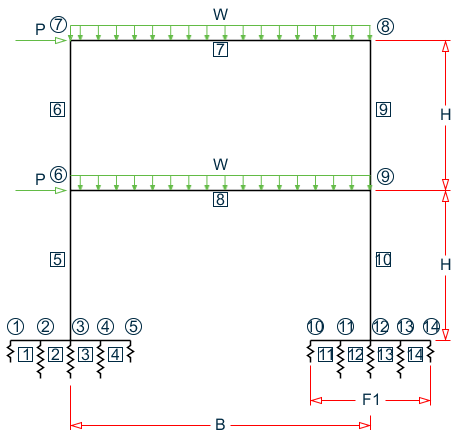
A portal frame type steel structure is sitting on concrete footings. The soil is to be considered as an elastic foundation. The value of soil subgrade reaction is known from which spring constants are calculated by multiplying the subgrade reaction by the tributary area of each modeled spring.
This problem is installed with the program by default to C:\Users\Public\Public Documents\STAAD.Pro CONNECT Edition\Samples\Sample Models\US\US-3 Soil Springs for Portal Frame.STD when you install the program.
Example Problem No. 3
Where:
- B = 20 ft, H = 10 ft, F1 = 4 ft, F2 = 8 ft
- P = 5 kips, w = 3 kips/ft
- Soil Subgrade Reaction = 250 kips/ft3
| Springs of Joints | Spring Constant |
|---|---|
|
1, 5, 10, & 14 (Edges) |
8 x 1 x 250 = 2,000 kips/ft |
|
2, 3, 4, 11, 12, & 13 (Interior) |
8 x 2 x 250 = 4,000 kips/ft |
Actual input is shown in bold lettering followed by explanation.
STAAD PLANE PORTAL ON FOOTING FOUNDATION
Every input has to start with the term STAAD. The term PLANE signifies that the structure is a plane frame structure and the geometry is defined through X and Y axes.
UNIT FT KIPS
Defines the input units for the data that follows.
    JOINT COORDINATES
    1   0.0  0.0  0.0  5  8.0  0.0 0.0
    6   4.0 10.0 0.0 ; 7  4.0 20.0 0.0
    8  24.0 20.0 0.0 ; 9  24.0 10.0 0.0
    10 20.0 0.0 0.0 14 28.0 0.0 0.0
Joint number followed by X, Y and Z coordinates are provided above. Since this is a plane structure, the Z coordinates are given as all zeros.
    MEMBER INCIDENCES
    1 1 2 4
    5 3 6 ; 6 6 7
    7 7 8 ; 8 6 9
    9 8 9 ; 10 9 12
    11 10 11 14
Defines the members by the joints to which they are connected.
    MEMBER PROPERTIES AMERICAN
    1 4 11 14 PRIS YD 1.0 ZD 8.0
    2 3 12 13 PRIS YD 2.0 ZD 8.0
    5 6 9 10 TA ST W10X33
    7 8 TA ST W12X26
The first two lines define member properties as prismatic (PRIS) followed by depth (YD) and width (ZD) values. The program will calculate the properties necessary to perform the analysis. See G.6.1 Prismatic Properties for additional information. Member properties for the remaining members are chosen from the British steel table. The term ST stands for standard single section.
    * E FOR STEEL IS 29,000 AND FOR CONCRETE 3000
    UNIT INCHES
    DEFINE MATERIAL START
    ISOTROPIC STEEL
    E 29000
    POISSON 0.3
    DENSITY 0.283e-003
    ALPHA 6e-006
    DAMP 0.03
    TYPE STEEL
    STRENGTH FY 36 FU 58 RY 1.5 RT 1.2
    ISOTROPIC CONCRETE
    E 3000
    POISSON 0.17
    DENSITY 8.68e-005
    ALPHA 5e-006
    DAMP 0.05
    G 1346.15
    TYPE CONCRETE
    STRENGTH FCU 4
    END DEFINE MATERIAL
    CONSTANTS
    MATERIAL STEEL MEMB 5 TO 10
    MATERIAL CONCRETE MEMB 1 TO 4 11 TO 14
The CONSTANT command initiates input for material constants like modulus of elasticity, Density, and Poisson's ratio. The length unit is changed from FT to INCH to facilitate the input in familiar units.
    UNIT FT
    SUPPORTS
    2 TO 4  11  TO  13  FIXED BUT MZ KFY 4000.
    1  5  10  14  FIXED BUT MZ KFY 2000.
The supports for the structure are specified above. The first set of joints are supports restrained in all directions except global moment-z (MZ). Also, a spring having a spring constant of 4,000 kip/ft is provided in the global Y direction at these nodes. The second set is similar to the former except for a different value of the spring constant.
LOADING 1 DEAD AND WIND LOAD COMBINED
Load case 1 is initiated followed by a title.
SELF Y -1.0
The selfweight of the structure is specified as acting in the global Y direction with a -1.0 factor.
Since global Y is vertically upwards, the -1.0 factor indicates that this load will act downwards.
    JOINT LOAD
    6 7  FX  5.0
Load 1 contains joint loads also. FX indicates that the load is a force in the global X direction.
    MEMBER LOAD
    7 8 UNI GY  -3.0
Load 1 contains member loads also. GY indicates that the load acts in the global Y direction. The term UNI stands for uniformly distributed load, and is applied on members 7 and 8, acting downwards.
PERFORM ANALYSIS
This command instructs the program to proceed with the analysis.
PRINT ANALYSIS RESULTS
The above PRINT command instructs the program to print analysis results which include joint displacements, member forces and support reactions.
FINISH
This command terminates the STAAD run.
Input File
STAAD PLANE PORTAL ON FOOTING FOUNDATION
UNIT FT KIPS
JOINT COORDINATES
1   0.0  0.0  0.0  5  8.0  0.0 0.0
6   4.0 10.0 0.0 ; 7  4.0 20.0 0.0
8  24.0 20.0 0.0 ; 9  24.0 10.0 0.0
10 20.0 0.0 0.0 14 28.0 0.0 0.0
MEMBER INCIDENCES
1 1 2 4
5 3 6 ; 6 6 7
7 7 8 ; 8 6 9
9 8 9 ;10 9 12
11 10 11 14
MEMBER PROPERTIES AMERICAN
1 4 11 14 PRIS YD 1.0 ZD 8.0
2 3 12 13 PRIS YD 2.0 ZD 8.0
5 6 9 10 TA ST W10X33
7 8 TA ST W12X26
* E FOR STEEL IS 29,000 AND FOR CONCRETE 3000
UNIT INCHES
DEFINE MATERIAL START
ISOTROPIC STEEL
E 29000
POISSON 0.3
DENSITY 0.283e-003
ALPHA 6e-006
DAMP 0.03
TYPE STEEL
STRENGTH FY 36 FU 58 RY 1.5 RT 1.2
ISOTROPIC CONCRETE
E 3000
POISSON 0.17
DENSITY 8.68e-005
ALPHA 5e-006
DAMP 0.05
G 1346.15
TYPE CONCRETE
STRENGTH FCU 4
END DEFINE MATERIAL
CONSTANTS
MATERIAL STEEL MEMB 5 TO 10
MATERIAL CONCRETE MEMB 1 TO 4 11 TO 14
UNIT FT
SUPPORTS
2 TO 4  11 TO 13 FIXED BUT MZ KFY 4000.
1 5 10 14 FIXED BUT MZ KFY 2000.
LOADING 1 DEAD AND WIND LOAD COMBINED
SELF Y -1.0
JOINT LOAD
6 7 FX 5.0
MEMBER LOAD
7 8 UNI GY -3.0
PERFORM ANALYSIS
PRINT ANALYSIS RESULTS
FINISH
STAAD Output File
                                                                  PAGE NO.    1
             ****************************************************
             *                                                  *
             *           STAAD.Pro CONNECT Edition              *
             *           Version  22.07.00.***                  *
             *           Proprietary Program of                 *
             *           Bentley Systems, Inc.                  *
             *           Date=    JUL  6, 2021                  *
             *           Time=    23:32: 4                      *
             *                                                  *
             *  Licensed to: Bentley Systems Inc                *
             ****************************************************
     1. STAAD PLANE PORTAL ON FOOTING FOUNDATION
INPUT FILE: US-3 Soil Springs for Portal Frame.STD
     2. UNIT FT KIPS
     3. JOINT COORDINATES
     4. 1   0.0  0.0  0.0  5  8.0  0.0 0.0
     5. 6   4.0 10.0 0.0 ; 7  4.0 20.0 0.0
     6. 8  24.0 20.0 0.0 ; 9  24.0 10.0 0.0
     7. 10 20.0 0.0 0.0 14 28.0 0.0 0.0
     8. MEMBER INCIDENCES
     9. 1 1 2 4
    10. 5 3 6 ; 6 6 7
    11. 7 7 8 ; 8 6 9
    12. 9 8 9 ;10 9 12
    13. 11 10 11 14
    14. MEMBER PROPERTIES AMERICAN
    15. 1 4 11 14 PRIS YD 1.0 ZD 8.0
    16. 2 3 12 13 PRIS YD 2.0 ZD 8.0
    17. 5 6 9 10 TA ST W10X33
    18. 7 8 TA ST W12X26
    19. * E FOR STEEL IS 29,000 AND FOR CONCRETE 3000
    20. UNIT INCHES
    21. DEFINE MATERIAL START
    22. ISOTROPIC STEEL
    23. E 29000
    24. POISSON 0.3
    25. DENSITY 0.283E-003
    26. ALPHA 6E-006
    27. DAMP 0.03
    28. TYPE STEEL
    29. STRENGTH FY 36 FU 58 RY 1.5 RT 1.2
    30. ISOTROPIC CONCRETE
    31. E 3000
    32. POISSON 0.17
    33. DENSITY 8.68E-005
    34. ALPHA 5E-006
    35. DAMP 0.05
    36. G 1346.15
    37. TYPE CONCRETE
    38. STRENGTH FCU 4
      PORTAL ON FOOTING FOUNDATION                             -- PAGE NO.    2
    39. END DEFINE MATERIAL
    40. CONSTANTS
    41. MATERIAL STEEL MEMB 5 TO 10
    42. MATERIAL CONCRETE MEMB 1 TO 4 11 TO 14
    43. UNIT FT
    44. SUPPORTS
    45. 2 TO 4  11 TO 13 FIXED BUT MZ KFY 4000.
    46. 1 5 10 14 FIXED BUT MZ KFY 2000.
    47. LOADING 1 DEAD AND WIND LOAD COMBINED
    48. SELF Y -1.0
    49. JOINT LOAD
    50. 6 7 FX 5.0
    51. MEMBER LOAD
    52. 7 8 UNI GY -3.0
    53. PERFORM ANALYSIS
            P R O B L E M   S T A T I S T I C S
            -----------------------------------
     NUMBER OF JOINTS         14  NUMBER OF MEMBERS      14
     NUMBER OF PLATES          0  NUMBER OF SOLIDS        0
     NUMBER OF SURFACES        0  NUMBER OF SUPPORTS     10
           Using 64-bit analysis engine.
           SOLVER USED IS THE IN-CORE ADVANCED MATH SOLVER
   TOTAL      PRIMARY LOAD CASES =     1, TOTAL DEGREES OF FREEDOM =      32
   TOTAL LOAD COMBINATION  CASES =     0  SO FAR.
    54. PRINT ANALYSIS RESULTS
  ANALYSIS RESULTS
      PORTAL ON FOOTING FOUNDATION                             -- PAGE NO.    3
   JOINT DISPLACEMENT (INCH RADIANS)    STRUCTURE TYPE = PLANE
   ------------------
 JOINT  LOAD   X-TRANS   Y-TRANS   Z-TRANS   X-ROTAN   Y-ROTAN   Z-ROTAN
      1    1    0.00000  -0.04256   0.00000   0.00000   0.00000  -0.00028
      2    1    0.00000  -0.04892   0.00000   0.00000   0.00000  -0.00023
      3    1    0.00000  -0.05439   0.00000   0.00000   0.00000  -0.00020
      4    1    0.00000  -0.05854   0.00000   0.00000   0.00000  -0.00017
      5    1    0.00000  -0.06134   0.00000   0.00000   0.00000  -0.00010
      6    1    0.32187  -0.07856   0.00000   0.00000   0.00000  -0.00483
      7    1    0.64023  -0.09085   0.00000   0.00000   0.00000  -0.00669
      8    1    0.62253  -0.10247   0.00000   0.00000   0.00000   0.00393
      9    1    0.32940  -0.08883   0.00000   0.00000   0.00000   0.00014
     10    1    0.00000  -0.03597   0.00000   0.00000   0.00000  -0.00055
     11    1    0.00000  -0.04884   0.00000   0.00000   0.00000  -0.00051
     12    1    0.00000  -0.06099   0.00000   0.00000   0.00000  -0.00049
     13    1    0.00000  -0.07163   0.00000   0.00000   0.00000  -0.00043
     14    1    0.00000  -0.08045   0.00000   0.00000   0.00000  -0.00035
      PORTAL ON FOOTING FOUNDATION                             -- PAGE NO.    4
   SUPPORT REACTIONS -UNIT KIPS FEET    STRUCTURE TYPE = PLANE
   -----------------
 JOINT  LOAD   FORCE-X   FORCE-Y   FORCE-Z     MOM-X     MOM-Y     MOM Z
      2    1      0.00     16.31      0.00      0.00      0.00      0.00
      3    1     -0.60     18.13      0.00      0.00      0.00      0.00
      4    1      0.00     19.51      0.00      0.00      0.00      0.00
     11    1      0.00     16.28      0.00      0.00      0.00      0.00
     12    1     -9.40     20.33      0.00      0.00      0.00      0.00
     13    1      0.00     23.88      0.00      0.00      0.00      0.00
      1    1      0.00      7.09      0.00      0.00      0.00      0.00
      5    1      0.00     10.22      0.00      0.00      0.00      0.00
     10    1      0.00      5.99      0.00      0.00      0.00      0.00
     14    1      0.00     13.41      0.00      0.00      0.00      0.00
      PORTAL ON FOOTING FOUNDATION                             -- PAGE NO.    5
   MEMBER END FORCES    STRUCTURE TYPE = PLANE
   -----------------
   ALL UNITS ARE -- KIPS FEET     (LOCAL )
  MEMBER  LOAD  JT     AXIAL   SHEAR-Y  SHEAR-Z   TORSION     MOM-Y      MOM-Z
      1    1     1      0.00      7.09     0.00      0.00      0.00       0.00
                 2      0.00     -4.69     0.00      0.00      0.00      11.79
      2    1     2      0.00     21.00     0.00      0.00      0.00     -11.79
                 3      0.00    -16.20     0.00      0.00      0.00      48.99
      3    1     3      0.00    -22.54     0.00      0.00      0.00     -67.92
                 4      0.00     27.34     0.00      0.00      0.00      18.05
      4    1     4      0.00     -7.82     0.00      0.00      0.00     -18.05
                 5      0.00     10.22     0.00      0.00      0.00       0.00
      5    1     3     56.87      0.60     0.00      0.00      0.00      18.93
                 6    -56.54     -0.60     0.00      0.00      0.00     -12.95
      6    1     6     29.01    -11.36     0.00      0.00      0.00     -50.40
                 7    -28.68     11.36     0.00      0.00      0.00     -63.23
      7    1     7     16.36     28.68     0.00      0.00      0.00      63.23
                 8    -16.36     31.84     0.00      0.00      0.00     -94.86
      8    1     6     -6.96     27.53     0.00      0.00      0.00      63.35
                 9      6.96     32.99     0.00      0.00      0.00    -117.94
      9    1     8     31.84     16.36     0.00      0.00      0.00      94.86
                 9    -32.17    -16.36     0.00      0.00      0.00      68.77
     10    1     9     65.16      9.40     0.00      0.00      0.00      49.17
                12    -65.49     -9.40     0.00      0.00      0.00      44.85
     11    1    10      0.00      5.99     0.00      0.00      0.00       0.00
                11      0.00     -3.59     0.00      0.00      0.00       9.59
     12    1    11      0.00     19.87     0.00      0.00      0.00      -9.59
                12      0.00    -15.07     0.00      0.00      0.00      44.54
     13    1    12      0.00    -30.08     0.00      0.00      0.00     -89.39
                13      0.00     34.88     0.00      0.00      0.00      24.42
     14    1    13      0.00    -11.01     0.00      0.00      0.00     -24.42
                14      0.00     13.41     0.00      0.00      0.00       0.00
      PORTAL ON FOOTING FOUNDATION                             -- PAGE NO.    6
   ************** END OF LATEST ANALYSIS RESULT **************
    55. FINISH
             *********** END OF THE STAAD.Pro RUN ***********
               **** DATE= JUL  6,2021   TIME= 23:32: 5 ****
         ************************************************************
         *   For technical assistance on STAAD.Pro, please visit    *
         *   http://www.bentley.com/en/support/                     *
         *                                                          *
         *   Details about additional assistance from               *
         *   Bentley and Partners can be found at program menu      *
         *   Help->Technical Support                                *
         *                                                          *
         *           Copyright (c) Bentley Systems, Inc.            *
         *                http://www.bentley.com                    *
         ************************************************************