EX. UK-26 Modeling a Rigid Diaphragm Using Master-Slave
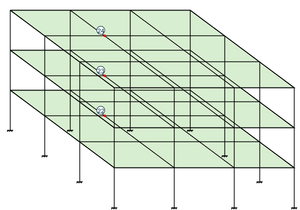
The structure in this example is a building consisting of member columns as well as floors made up of beam members and plate elements. Using the master-slave command, the floors are specified to be rigid diaphragms for in-plane actions but flexible for bending actions.
This problem is installed with the program by default to C:\Users\Public\Public Documents\STAAD.Pro CONNECT Edition\Samples\Sample Models\UK\UK-26 Modeling a Rigid Diaphragm Using Master-Slave.STD when you install the program.
    STAAD SPACE
    *MODELING RIGID DIAPHRAGMS USING MASTER SLAVE
Every STAAD input file has to begin with the word STAAD. The word SPACE signifies that the structure is a space frame and the geometry is defined through X, Y and Z axes. The second line is an optional title to identify this project.
UNITS KIP FT
Specify units for the following data.
    JOINT COORD
    1 0 0 0 4 0 48 0
    REPEAT 3 24 0 0
    REPEAT ALL 3 0 0 24
    DELETE JOINT 21 25 37 41
The joint numbers and coordinates are specified above. The unwanted joints, created during the generation process used above, are then deleted.
    MEMBER INCI
    1 1 2 3 ; 4 5 6 6 ; 7 9 10 9 ; 10 13 14 12
    13 17 18 15 ; 22 29 30 24 ; 25 33 34 27
    34 45 46 36 ; 37 49 50 39 ; 40 53 54 42
    43 57 58 45 ; 46 61 62 48 ; 49 2 6 51
    52 6 10 54 ; 55 10 14 57 ; 58 18 22 60
    61 22 26 63 ; 64 26 30 66 ; 67 34 38 69
    70 38 42 72 ; 73 42 46 75 ; 76 50 54 78
    79 54 58 81 ; 82 58 62 84 ; 85 18 2 87
    88 22 6 90 ; 91 26 10 93 ; 94 30 14 96
    97 34 18 99 ; 100 38 22 102 ; 103 42 26 105
    106 46 30 108 ; 109 50 34 111 ; 112 54 38 114
    115 58 42 117 ; 118 62 46 120
The MEMBER INCIDENCE specification is used for specifying MEMBER connectivities.
    ELEMENT INCI
    152 50 34 38 54 TO 154
    155 54 38 42 58 TO 157
    158 58 42 46 62 TO 160
    161 34 18 22 38 TO 163
    164 38 22 26 42 TO 166
    167 42 26 30 46 TO 169
    170 18 2 6 22 TO 172
    173 22 6 10 26 TO 175
    176 26 10 14 30 TO 178
The ELEMENT INCIDENCE specification is used for specifying plate element connectivities.
    MEMBER PROPERTIES AMERICAN
    1 TO 15 22 TO 27 34 TO 48 TA ST W14X90
    49 TO 120 TABLE ST W27X84
All members are WIDE FLANGE sections whose properties are obtained from the built in American steel table.
    ELEMENT PROP
    152 TO 178 THICK 0.75
The thickness of the plate elements is specified above.
    UNIT INCHES
    DEFINE MATERIAL START
    ISOTROPIC STEEL
    E 29000
    POISSON 0.3
    DENSITY 283e-006
    ALPHA 6e-006
    DAMP 0.03
    TYPE STEEL
    STRENGTH FY 36 FU 58 RY 1.5 RT 1.2
    ISOTROPIC CONCRETE
    E 3150
    POISSON 0.17
    DENSITY 8.68e-005
    ALPHA 5e-006
    DAMP 0.05
    G 1346.15
    TYPE CONCRETE
    STRENGTH FCU 4
    END DEFINE MATERIAL
    UNIT FEET
    CONSTANTS
    MATERIAL STEEL MEMB 1 TO 15 22 TO 27 34 TO 120
    BETA 90.0 MEMB 13 14 15 22 TO 27 34 TO 39
    MATERIAL CONCRETE MEMB 152 TO 178
The DEFINE MATERIAL command is used to specify material properties and the CONSTANT is used to assign the material to all members. The orientation of some of the members is set using the BETA angle command.
    SUPPORTS
    1 TO 17 BY 4 29 33 45 TO 61 BY 4 FIXED
The supports at the above mentioned joints are declared as fixed.
    SLAVE DIA ZX MASTER 22 JOINTS YR 15.0 17.0
    SLAVE DIA ZX MASTER 23 JOINTS YR 31.0 33.0
    SLAVE DIA ZX MASTER 24 JOINTS YR 47.0 49.0
The three floors of the structure are specified to act as rigid diaphragms in the ZX plane with the corresponding master joint specified. The associated slave joints in a floor are specified by the YRANGE parameter. The floors may still resist out-of-plane bending actions flexibly.
    LOADING 1 LATERAL LOADS
    JOINT LOADS
    2 3 4 14 15 16 50 51 52 62 63 64 FZ 10.0
    6 7 8 10 11 12 18 19 20 30 31 32 FZ 20.0
    34 35 36 46 47 48 54 55 56 58 59 60 FZ 20.0
    22 23 24 26 27 28 38 39 40 42 43 44 FZ 40.0
The above data describe a static load case. It consists of joint loads in the global Z direction.
    LOADING 2 TORSIONAL LOADS
    JOINT LOADS
    2 3 4 50 51 52 FZ 5.0
    14 15 16 62 63 64 FZ 15.0
    6 7 8 18 19 20 FZ 10.0
    10 11 12 30 31 32 FZ 30.0
    34 35 36 54 55 56 FZ 10.0
    46 47 48 58 59 60 FZ 30.0
    22 23 24 38 39 40 FZ 20.0
    26 27 28 42 43 44 FZ 60.0
The above data describe a static load case. It consists of joint loads that create a torsional loading on the structure.
    LOADING 3 DEAD LOAD
    ELEMENT LOAD
    152 TO 178 PRESS GY -1.0
The above data describe a static load case. It consists of plate element pressure on a floor in the negative global Y direction.
PERFORM ANALYSIS
The above command instructs the program to proceed with the analysis.
    PRINT JOINT DISP LIST 4 TO 60 BY 8
    PRINT MEMBER FORCES LIST 116 115
    PRINT SUPPORT REACTIONS LIST 9 57
Print displacements at selected joints, then print member forces for two members, then print support reactions at selected joints.
FINISH
The STAAD run is terminated.
Input File
STAAD SPACE
*MODELING RIGID DIAPHRAGMS USING MASTER SLAVE
UNITS KIP FT
JOINT COORD
1 0 0 0 4 0 48 0
REPEAT 3 24 0 0
REPEAT ALL 3 0 0 24
DELETE JOINT 21 25 37 41
MEMBER INCI
1 1 2 3 ; 4 5 6 6 ; 7 9 10 9 ; 10 13 14 12
13 17 18 15 ; 22 29 30 24 ; 25 33 34 27
34 45 46 36 ; 37 49 50 39 ; 40 53 54 42
43 57 58 45 ; 46 61 62 48 ; 49 2 6 51
52 6 10 54 ; 55 10 14 57 ; 58 18 22 60
61 22 26 63 ; 64 26 30 66 ; 67 34 38 69
70 38 42 72 ; 73 42 46 75 ; 76 50 54 78
79 54 58 81 ; 82 58 62 84 ; 85 18 2 87
88 22 6 90 ; 91 26 10 93 ; 94 30 14 96
97 34 18 99 ; 100 38 22 102 ; 103 42 26 105
106 46 30 108 ; 109 50 34 111 ; 112 54 38 114
115 58 42 117 ; 118 62 46 120
ELEMENT INCI
152 50 34 38 54 TO 154
155 54 38 42 58 TO 157
158 58 42 46 62 TO 160
161 34 18 22 38 TO 163
164 38 22 26 42 TO 166
167 42 26 30 46 TO 169
170 18  2  6 22 TO 172
173 22  6 10 26 TO 175
176 26 10 14 30 TO 178
MEMBER PROPERTIES AMERICAN
1 TO 15 22 TO 27 34 TO 48 TA ST W14X90
49 TO 120 TABLE ST W27X84
ELEMENT PROP
152 TO 178 THICK 0.75
UNIT INCHES
DEFINE MATERIAL START
ISOTROPIC STEEL
E 29000
POISSON 0.3
DENSITY 283e-006
ALPHA 6e-006
DAMP 0.03
TYPE STEEL
STRENGTH FY 36 FU 58 RY 1.5 RT 1.2
ISOTROPIC CONCRETE
E 3150
E 2916.7
POISSON 0.17
POISSON 0.12
DENSITY 8.68e-005
ALPHA 5e-006
DAMP 0.05
G 1346.15
TYPE CONCRETE
STRENGTH FCU 4
END DEFINE MATERIAL
CONSTANTS
MATERIAL STEEL MEMB 1 TO 15 22 TO 27 34 TO 120
BETA 90.0 MEMB 13 14 15 22 TO 27 34 TO 39
MATERIAL CONCRETE MEMB 152 TO 178
SUPPORTS
1 TO 17 BY 4 29 33 45 TO 61 BY 4 FIXED
SLAVE DIA ZX MASTER 22 JOINTS YR 15.0 17.0
SLAVE DIA ZX MASTER 23 JOINTS YR 31.0 33.0
SLAVE DIA ZX MASTER 24 JOINTS YR 47.0 49.0
LOADING 1 LATERAL LOADS
JOINT LOADS
2 3 4 14 15 16 50 51 52 62 63 64 FZ 10.0
6 7 8 10 11 12 18 19 20 30 31 32 FZ 20.0
34 35 36 46 47 48 54 55 56 58 59 60 FZ 20.0
22 23 24 26 27 28 38 39 40 42 43 44 FZ 40.0
LOADING 2 TORSIONAL LOADS
JOINT LOADS
2 3 4 50 51 52 FZ 5.0
14 15 16 62 63 64 FZ 15.0
6 7 8 18 19 20 FZ 10.0
10 11 12 30 31 32 FZ 30.0
34 35 36 54 55 56 FZ 10.0
46 47 48 58 59 60 FZ 30.0
22 23 24 38 39 40 FZ 20.0
26 27 28 42 43 44 FZ 60.0
LOADING 3 DEAD LOAD
ELEMENT LOAD
152 TO 178 PRESS GY -1.0
PERFORM ANALYSIS
PRINT JOINT DISP LIST 4 TO 60 BY 8
PRINT MEMBER FORCES LIST 116 115
PRINT SUPPORT REACTIONS LIST 9 57
FINISH
STAAD Output File
                                                                  PAGE NO.    1
             ****************************************************
             *                                                  *
             *           STAAD.Pro CONNECT Edition              *
             *           Version  22.00.00.**                   *
             *           Proprietary Program of                 *
             *           Bentley Systems, Inc.                  *
             *           Date=    DEC 13, 2018                  *
             *           Time=    10:47: 1                      *
             *                                                  *
             *  Licensed to: Bentley Systems Inc                *
             ****************************************************
     1. STAAD SPACE
INPUT FILE: UK-26 Modeling a Rigid Diaphragm Using Master-Slave.STD
     2. *MODELING RIGID DIAPHRAGMS USING MASTER SLAVE
     3. UNITS KIP FT
     4. JOINT COORD
     5. 1 0 0 0 4 0 48 0
     6. REPEAT 3 24 0 0
     7. REPEAT ALL 3 0 0 24
     8. DELETE JOINT 21 25 37 41
     9. MEMBER INCI
    10. 1 1 2 3 ; 4 5 6 6 ; 7 9 10 9 ; 10 13 14 12
    11. 13 17 18 15 ; 22 29 30 24 ; 25 33 34 27
    12. 34 45 46 36 ; 37 49 50 39 ; 40 53 54 42
    13. 43 57 58 45 ; 46 61 62 48 ; 49 2 6 51
    14. 52 6 10 54 ; 55 10 14 57 ; 58 18 22 60
    15. 61 22 26 63 ; 64 26 30 66 ; 67 34 38 69
    16. 70 38 42 72 ; 73 42 46 75 ; 76 50 54 78
    17. 79 54 58 81 ; 82 58 62 84 ; 85 18 2 87
    18. 88 22 6 90 ; 91 26 10 93 ; 94 30 14 96
    19. 97 34 18 99 ; 100 38 22 102 ; 103 42 26 105
    20. 106 46 30 108 ; 109 50 34 111 ; 112 54 38 114
    21. 115 58 42 117 ; 118 62 46 120
    22. ELEMENT INCI
    23. 152 50 34 38 54 TO 154
    24. 155 54 38 42 58 TO 157
    25. 158 58 42 46 62 TO 160
    26. 161 34 18 22 38 TO 163
    27. 164 38 22 26 42 TO 166
    28. 167 42 26 30 46 TO 169
    29. 170 18  2  6 22 TO 172
    30. 173 22  6 10 26 TO 175
    31. 176 26 10 14 30 TO 178
    32. MEMBER PROPERTIES AMERICAN
    33. 1 TO 15 22 TO 27 34 TO 48 TA ST W14X90
    34. 49 TO 120 TABLE ST W27X84
    35. ELEMENT PROP
    36. 152 TO 178 THICK 0.75
    37. UNIT INCHES
    38. DEFINE MATERIAL START
      STAAD SPACE                                              -- PAGE NO.    2
    *MODELING RIGID DIAPHRAGMS USING MASTER SLAV
    39. ISOTROPIC STEEL
    40. E 29000
    41. POISSON 0.3
    42. DENSITY 283E-006
    43. ALPHA 6E-006
    44. DAMP 0.03
    45. TYPE STEEL
    46. STRENGTH FY 36 FU 58 RY 1.5 RT 1.2
    47. ISOTROPIC CONCRETE
    48. E 3150
    49. E 2916.7
    50. POISSON 0.17
    51. POISSON 0.12
    52. DENSITY 8.68E-005
    53. ALPHA 5E-006
    54. DAMP 0.05
    55. G 1346.15
    56. TYPE CONCRETE
    57. STRENGTH FCU 4
    58. END DEFINE MATERIAL
    59. CONSTANTS
    60. MATERIAL STEEL MEMB 1 TO 15 22 TO 27 34 TO 120
    61. BETA 90.0 MEMB 13 14 15 22 TO 27 34 TO 39
    62. MATERIAL CONCRETE MEMB 152 TO 178
    63. SUPPORTS
    64. 1 TO 17 BY 4 29 33 45 TO 61 BY 4 FIXED
    65. SLAVE DIA ZX MASTER 22 JOINTS YR 15.0 17.0
 **ERROR-NO VALID SLAVE JOINTS IN RANGE SPECIFIED.
    66. SLAVE DIA ZX MASTER 23 JOINTS YR 31.0 33.0
 **ERROR-NO VALID SLAVE JOINTS IN RANGE SPECIFIED.
    67. SLAVE DIA ZX MASTER 24 JOINTS YR 47.0 49.0
 **ERROR-NO VALID SLAVE JOINTS IN RANGE SPECIFIED.
    68. LOADING 1 LATERAL LOADS
             *********** END OF THE STAAD.Pro RUN ***********
               **** DATE= DEC 13,2018   TIME= 10:47: 1 ****
      STAAD SPACE                                              -- PAGE NO.    3
    *MODELING RIGID DIAPHRAGMS USING MASTER SLAV
         ************************************************************
         *   For technical assistance on STAAD.Pro, please visit    *
         *   http://www.bentley.com/en/support/                     *
         *                                                          *
         *   Details about additional assistance from               *
         *   Bentley and Partners can be found at program menu      *
         *   Help->Technical Support                                *
         *                                                          *
         *      Copyright (c) 1997-2017 Bentley Systems, Inc.       *
         *                http://www.bentley.com                    *
         ************************************************************