TR.5 Set Command Specification
This command allows you to set various general specifications for the analysis/design run.
General Format
SET { NL i1 | {DISPLACEMENT i2 | PDELTA TOLERANCE i9} | SDAMP i3 | WARP i4 | ITERLIM i5 | PRINT i7 | NOPRINT DIRECT | SHEAR | ECHO { ON | OFF } | GUI i6 | { Z | Y } UP | DEFLECTION CUTOFF f1 | FLOOR LOAD TOLERANCE f2 | EIGEN METHOD { LANCZOS | RITZ} }
Where:
Description
The following SET commands contain values with associated units and should appear after a UNIT command and before the first JOINT command.
| Command | Parameter | Description |
|---|---|---|
| SET NL | i1 | The
SET NL command is used in a multiple analysis
run if you want to add more primary load cases after one analysis has been
performed. Specifically, for those examples which use the
CHANGE command (see
TR.38 Change Specification), if you want to add more primary load cases, the NL value
should be set to the maximum number (or slightly more) with the
SET NL command. The program will then be able to
set aside additional memory space for information to be added later. This
command should be provided before any joint, member or load specifications.
The value for i1 is the maximum number of primary load cases (NL). This value should not be much greater than the maximum number of primary load cases actually used in the model. |
|
SET DISPLACEMENT |
i2 | For
PDELTA ANALYSIS with
CONVERGE option there are two convergence
methodologies to choose from (refer to
TR.37.2
P-Delta Analysis Options for additional information)
Note: Both
i2 and
i9 are the P-Delta Convergence
criteria input. There are two methods available, enter
SET DISPLACEMENT
i2 or
SET PDELTA TOL
i9 . Enter only one.
|
|
PDELTA TOLERANCE |
i9 | |
| SET DEFLECTION CUTOFF | f1 | Used to arrest huge
displacements in minor axis due to small delta effects.
f1 = If the absolute value of the maximum section displacement is less than f1 after two iterations; then it is converged. Rapidly diverging minor axis displacement will not occur until after two iterations. f1 is in current length units. |
| SET FLOOR LOAD TOLERANCE | f2 |
Used to specify the tolerance for out of plane nodes in a floor load. The program expects all nodes to lie in the same plain. If there is any minor variation in coordinates of the nodes, the program will excluded floor panels connected to those nodes. Hence, a tolerance value is used to so that all nodes with in the range (min. Y and min Y + tolerance). Refer to TR.32.4.3 Floor Load Specification for details on specifying a plane for floor loads. f2 = tolerance value used |
The following SET commands have dimensionless input
| Command | Parameter | Description |
|---|---|---|
| SET SDAMP | i3 | The
SET SDAMP command will allow the damping of springs to
be considered in computing the composite modal damping for each mode in a
dynamic solution. This command is not used unless CDAMP ratios are also entered
for the members and elements in the CONSTANTS command. Composite damping is
generally only used if there are many modes in the dynamic solution and there
are a wide range of damping ratios in the springs, members, or elements.
i3 = the damping ratio to be used for all springs in computing the modal composite damping in dynamics. |
| SET WARP | i4 | The SET WARP command will allow the I section member end warping restraint to be considered in calculating the torsional stiffness rigidity. Full or partial or no warping restraint are allowed. |
| SET ITERLIM | i5 |
The SET ITERLIM command is for raising the maximum iteration limit above the default of 10 in tension/compression iterations. Since this iterative procedure will not necessarily converge, this option of more iterations may not help and should be used with caution. The minimum iteration limit that may be entered is 3. The maximum number if 150. Any value higher than this will be replaced with 150. After any tension/compression analysis, the output file (file extension .ANL) should be scanned for warnings of non-convergence. Do not use results from non-converged cases. i5 = Maximum number of tension/compression iterations. |
| SET PRINT | i7 | The following values can be used
to suppress the described warnings or include the described additional results
in the output:
i7 = Used to suppress some warning messages or to include additional output. |
| SET NOPRINT DIRECT | (n/a) | Used to turn off the tau-b details in the output file when running a Direct Analysis (refer to TR.37.5 Direct Analysis). |
| SET SHEAR | (n/a) | The SET SHEAR command is for omitting the additional pure shear distortion stiffness terms in forming beam member stiffnesses. With this command you can exactly match simple textbook beam theory results. |
| SET ECHO | (n/a) | The SET ECHO ON command will activate and the SET ECHO OFF command will deactivate the echoing of input file commands in the output file. In the absence of the SET ECHO command, input file commands will be echoed back to the output file. |
| SET GUI | i6 | After the calculations are
completed, and before the Analysis window is closed, the program creates
several files for the purpose of displaying results in the post processing
mode. In large models, this can be a time consuming process. If the user's goal
is to look at results in the output file only (file extension
.ANL) and does not intend to go into the
post-processing mode, he/she could instruct the program to skip the process of
creating those files. The
SET GUI 1 may be specified immediately before
the
FINISH command, or somewhere near the beginning
of the file after
STAAD SPACE.
i6 = 1, Bypass forming data and files needed for post-processing. |
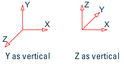
| SET { Z | Y } UP | (n/a) |
By default, the Y-axis is the vertical axis. However, the SET Z UP command may be used to model situations where Z-axis represents the vertical axis (direction of gravity load) of the structure. This situation may arise if the input geometry is created through some CAD software. This command will affect the default BETA angle specification. However, BETA can be set to a certain value for all members parallel to a particular global axis by using the MEMBER X (or Y or Z) type of listing. For additional information, see the CONSTANTs specification (see TR.26 Specifying and Assigning Material Constants). |
| SET STAR | i | Instructs the program which solver to use. Refer to TR.0 STAAD Commands and Input Instructions for additional
information.
|
| SET EIGEN METHOD { LANCZOS | RITZ } | (n/a) |
LANCZOS — Instructs the solver to use Arnoldi/Lanczos method for extraction of eigen vectors. RITZ — Use load dependent Ritz vectors method for extraction of eigen vectors. The use of either the Arnoldi/Lanczos method or the Ritz method require a STAAD.Pro Advanced license. If neither method is specified, the default method of Subspace-iteration is used. |
Less frequently used SET commands
The following table contains a list of less frequently used SET commands
| Command | Default | Description |
|---|---|---|
| SET INTERPOLATION { LIN | LOG } | LIN or LOG for spectra | |
| SET NOSECT | No section results will be calculated | |
| SET PLATE FLATNESS TOLERANCE f |
Used to so specify a tolerance for the plate warping check. By default, plate warping is reported when there is a 30 degree angle (or larger) between the normal to two triangles which are formed by splitting a quad element. This splitting can be done two ways so there are four triangles. If any have more than the tolerance angle (in degrees) between them, then an error is reported. The value f is given in degrees. |
|
| SET INPLANE ROTATION | In-plane rotation (MX) in plates will be ignored. | |
| SET ENDFACTOR f | 1.0 or -1.0 for combining spectrum cases | |
| SET PROFILE s2 | A command to define the path of the folder that contains the collection of databases of section property data in SQLite (.DB3) files. Note also that the GUI will use this as the location of the section profile databases. | |
| SET NOWARNING | Switches off some warning messages. | |
| SET USE DLL | Used plugin .dll for design (ACI code only) | |
| SET RIGID DIAPHRAGM i | 150 | The number of diaphragms used. This command is used to reserve memory for the maximum number of diaphragms that may be defined in the model. See section TR.28.2 Floor Diaphragm for more information on defining and using floor diaphragms in an analysis. |
| SET INCLINED REACTION | To obtain reactions at inclined supports in the inclined axis system. | |
| SET GROUP DUPLICATES | Followed by an integer value which is used to specify the number of groups to which one model entity (node, member, plate, or solid object) may belong. Must be in the range of four to 100, inclusive. The default value is 10 groups. | |
| SET CG TXT | Used to print section forces for generated load combinations to an external text file. See TR.35 Load Combination Specification for additional details. This command should be used only for review of data and not in normal circumstances as the resulting text file can be very large. | |
| SET RS TXT | Used to print section forces for each of the modes for response spectrum load cases to an external text file. See TR.35 Load Combination Specification for additional details. This command should be used only for review of data and not in normal circumstances as the resulting text file can be very large. | |
| SET NF TXT | Used to print section forces for each member corresponding to the critical load combination generation case to an external text file. See TR.35 Load Combination Specification for additional details. This command should be used only for review of data and not in normal circumstances as the resulting text file can be very large. | |
| SET THCOPYS i |
i = 4 (default) i = number of TYPES that a given node-dof may be a part of in time history loading. |
|
| SET WARNING { ON | OFF } | Used to suppress warnings in the output (.anl) file when set to OFF (ON is default). | |
| SET NOTE { ON | OFF } | Used to suppress notes in the output (.anl) file when set to OFF (ON is default). | |
| SET DIVISION i | Set the number of divisions used in meshing for surfaces (default is 10) | |
| SET MULTI { 1 | 2 } | If multi-linear analysis fails to converge, try entering SET MULTI 2 and re-running. | |
| SET PARTICIPATION FACTOR | Compute participation factors as a numeric value in addition to the percentage of total mass usually displayed. | |
| SET BUCKLING MODES i | Number of buckling modes computed with advanced solver. Default is i= 4. | |
| SET BYPASS { DIS | FOR | EJS | EJF } |
Bypass generating certain outputs for the graphical user interface.
|
|
| SET LOAD PLATE | Include loads applied to inactive plates. |