Used to assign prismatic cross sections to members.
Opens when the
Beam Profiles > Prismatic Profiles tool is selected in the
Specifications group on the
Specification ribbon tab.
Note: The
Properties - Whole Structure dialog
also opens simultaneously so that some of the other options available from that
dialog may be utilized.
Circle tab
| Setting | Description |
|---|
| YD
|
Section diameter.
|
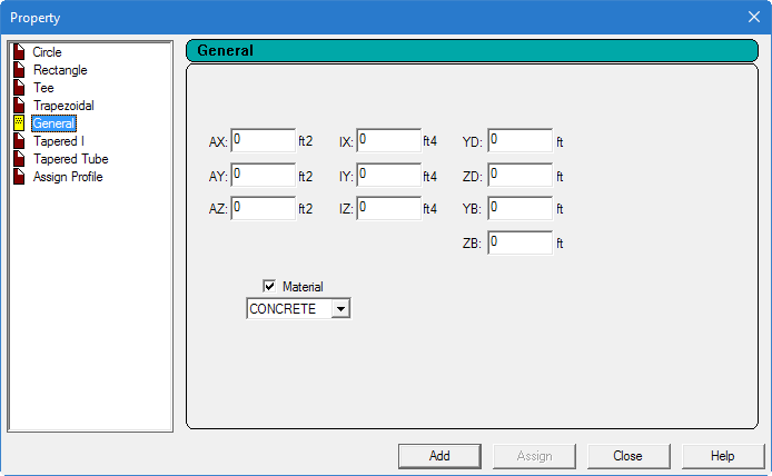
| Material
|
Check this box and select the material from the drop
down list if the new member property tag should include the material constants.
|
Rectangle
tab
| Setting | Description |
|---|
| YD
|
Depth of the member in local y direction.
|
| ZD
|
Width of the member in the local z direction.
|
Tee tab
| Setting | Description |
|---|
| YD
|
Depth of the member in local y direction.
|
| ZD
|
Width of the flange.
|
| YB
|
Depth of the stem (web).
|
| ZB
|
Width of the stem (web).
|
Trapezoidal
tab
| Setting | Description |
|---|
| YD
|
Depth of the member in local y direction.
|
| ZD
|
Top width.
|
| ZB
|
Bottom width.
|
General tab
| Setting | Description |
|---|
| AX
|
Cross sectional area of the member.
|
| AY
|
Effective shear area in local y-axis.
|
| AZ
|
Effective shear area in local z-axis.
|
| IX
|
Torsional constant.
|
| IY
|
Moment of inertia about local y-axis.
|
| IZ
|
Moment of inertia about local z-axis (usually
major).
|
| YD
|
Depth of the member in local y direction. Used as the
diameter of section for circular members.
|
| ZD
|
Depth of the member in local z direction. If ZD is
not provided and YD is provided, the section will be assumed to be circular.
|
| YB
|
Depth of stem for T-section.
|
| ZB
|
Width of stem for Tee section or bottom width for
trapezoidal section.
|
Tapered I
tab
| Setting | Description |
|---|
| F1
|
Depth of section at start node.
|
| F2
|
Thickness of web.
|
| F3
|
Depth of section at end node.
Note: F3 should be less than F1 (i.e., the section should
decrease in depth from start to end). You must provide the member incidences
accordingly.
|
| F4
|
Width of top flange.
|
| F5
|
Thickness of top flange.
|
| F6
|
Width of bottom flange. Defaults to F4 is zero.
|
| F7
|
Thickness of bottom flange. Defaults to F5 if zero.
|
Tapered Tube tab
| Setting | Description |
|---|
| Type of Section
|
Select one of the profile shapes:
- Round
- Hexdecagonal – 16-sided
- Dodecagonal – 12-sided
- Octagonal – 8-sided
- Hexagonal – 6-sided
- Square – 4-sided
|
| d1
|
Depth of section at start of member.
|
| d2
|
Depth of section at end of member.
|
| th
|
Thickness of section (constant throughout the member
length).
|
Notes:
- Section properties are
calculated using the rules applicable for thin-walled sections.
-
Shear deformation is not considered for tapered
I-Beams and tapered poles. This means that the
SET SHEAR command has no effect on the deformation
computed for members with these cross sections.
Assign Profile tab
Used to instruct the program to select a suitable steel section based
on a profile classification, such as beam, column, double-angle, etc.
| Setting | Description |
|---|
| Select Profile Specification
|
Specify a profile by selecting one of the options:
- Angle
- Double Angle
- Beam
- Column
- Channel
The program will then assign a section based on that profile
from the relevant built-in Steel table.
|