V. AISC 360-16 Tapered I Section
Verify the axial compression capacity, flexure capacity, and interaction ratio of a tapered I section member per both the LRFD and ASD methods of the AISC 360-16 code.
Details
A 5' × 5' portal frame consists of W12x72 columns and a steel tapered member for the beam.
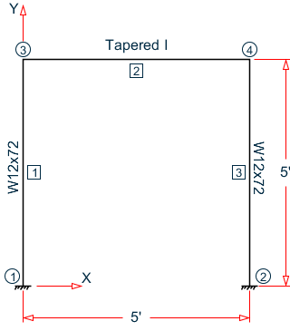
- A uniformly distributed load of -3.5 k/ft along the beam in the global Y direction.
- Lateral loads at the top of the left column of 50 kips in the global X direction and 25 kips in the global Z direction (out of plane).
- Lateral loads at the top of the right column of -50 kips in the global X direction and 45 kips in the global Z direction (out of plane).
- A concreted load of -100 kips in the global Y direction and a concentrated torque of 9 in·kips at mid-span of the beam.
- E = 29,000 ksi
- Fy = 50 ksi
Validation
Design Forces
- Mz = 32.26 in·kips, Fy = 8.755 kips
- Mz = 677.6 in·kips, My = 2.942 in·kips, Mx = 5.106 in·kips, Fy = 22.49 kips, Fz = 0.098 kips, Fx = 24.70 kips
- Mz = 275.9 in·kips, Mx = 4.497 in·kips, Fy = 50.23 kips, Fx = 5.473 kips
- Mz = 654.5 in·kips, My = 5.298 in·kips, Mx = 9.192 in·kips, Fy = 22.50 kips, Fz = 0.177 kips, Fx = 24.35 kips
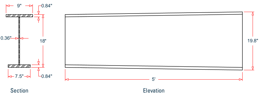
Section Properties
The section at the left end (D = 18 in.) has the following properties:
- Web height, dw = 18 - 2×0.84 = 16.32 in.
- Area, Ag = (0.84)(9 + 7.5) + 16.32 (0.36) = 19.74 in2
- Shear area in local y, Ay = 16.32(0.36) = 5.875 in2
- Shear area in local x, Ax = 0.84(9 + 7.5) = 13.86 in2
- Dist to centroid y,
- Moment of inertia about major axis,
- Moment of inertia about minor axis,
- Elastic section modulus about major axis top flange fiber,
- Elastic section modulus about major axis bottom flange fiber,
- Elastic section modulus about minor axis,
- Radius of gyration about major axis,
- Radius of gyration about minor axis,
- Location of the plastic neutral axis,
- Plastic section modulus about major axis,
- Plastic section modulus about minor axis,
- Torsional constant,
Section Classification
Flange in compression
Per Table B4.1a, , therefore flanges are non-slender for compression.
Web in compression
Per Table B4.1a, Case 5, , therefore the web is slender for compression.
Flange in bending (use half the longer flange width as the outstanding width):
Per Table 1.b, Case 11, , therefore flange is compact for bending.
Web in bending
Per Table 1.b, Case 15, , therefore web is compact for bending.
Compression Capacity
About X Axis:
| (Eq. E3-4) |
| (Eq. E3-2) |
Since the web is slender, use the effective area. The effective width imperfection adjustment factors (Table E7.1):
c1 = 0.18
c2 = 1.31
| (Eq. E7-5) |
Therefore, the effective depth of the web in compression for the effective area:
| (Eq. E7-3) |
The reduced area of the section then becomes:
| Pnx = Ae× Fcrx = 18.84 × 49.77 = 937.4 kips | (Eq. E7-1) |
About Y Axis:
| (Eq. E3-4) |
| (Eq. E3-2) |
Therefore, the effective depth of the web in compression for the effective area:
| (Eq. E7-3) |
The reduced area of the section then becomes:
| Pny = Ae× Fcry = 18.93 × 46.88 = 887.4 kips | (Eq. E7-1) |
- The ultimate compression capacity (LRFD) = ϕcPn = 0.9 × 887.4 = 798.3 kips
- The allowable compression capacity (ASD) = Pn/Ωc = 887.4 / 1.67 = 531.4 kips
Calculate Bending Capacity
Bending capacity in plastic yielding about Y axis:
My = Fy × Zy = 50 × 29.35 = 1,468 in·kips > 1.6Fy × Sy = 1.6 (50) (17.92) = 1,434 in·kips
Use My =1,434 in·kips
- The ultimate bending capacity (LRFD) = ϕbMy = 0.9 × 1,434 = 1,290 in·kips
- The allowable bending capacity (ASD) = My/Ωb = 1,434 / 1.67 = 858.4 in·kips
Bending capacity in plastic yielding about X axis:
Calculate the bending strength reduction factor:
| (Eq. F5.6) |
| = | ||
| = |
| (Eq. F5.6) |
Mn = Rpg × Fy × Syc = 1.0 × 50 × 120 = 6,000 in·kips
- The ultimate bending capacity (LRFD) = ϕbMy = 0.9 × 6,000 = 5,400 in·kips
- The allowable bending capacity (ASD) = My/Ωb = 5,000 / 1.67 = 3,593 in·kips
Lateral-torsional buckling about the X axis:
| (Eq. F4-7) |
| = |
Thus, and . Therefore, lateral-torsional buckling must be checked.
| (Eq. F4-8) |
| = | ||
| = |
As Lr < Lb = 60 < Lp, the nominal moment capacity is:
| (Eq. F4-2) |
| = | ||
| = | ||
| = | ||
| = | ||
| = |
- The ultimate bending capacity (LRFD) = ϕbMy = 0.9 × 6,983 = 6,285 in·kips
- The allowable bending capacity (ASD) = My/Ωb = 6,983 / 1.67 = 4,181 in·kips
Compression flange local yielding does not apply as the flanges are compact.
Interaction Ratio for Bending and Compression
Check the interaction ratio for Load Case 2:
So use Eq. H1-1b for both methods: .
Results
| Result Type | Reference | STAAD.Pro | Difference | Comments | |
|---|---|---|---|---|---|
| LRFD | Compression capacity (kips) | 798.3 | 798.8 | negligible | |
| Major axis bending capacity (in·kips) | 5,400 | 5,399 | negligible | ||
| Minor axis bending capacity (in·kips) | 1,290 | 1,290 | none | ||
| Interaction ratio | 0.143 | 0.143 | none | ||
| ASD | Compression capacity (kips) | 531.4 | 531.48 | negligible | |
| Major axis bending capacity (in·kips) | 3,593 | 3,592.4 | negligible | ||
| Minor axis bending capacity (in·kips) | 858.4 | 858.28 | negligible | ||
| Interaction ratio | 0.215 | 0.215 | none | ||
STAAD.Pro Input
The following design parameters are used:
The remaining parameters all use their default values.
The file C:\Users\Public\Public Documents\STAAD.Pro CONNECT Edition\Samples\ Verification Models\09 Steel Design\US\AISC\AISC 360-16 Tapered I Section.STD is typically installed with the program.
STAAD SPACE
START JOB INFORMATION
ENGINEER DATE 14-Jan-21
END JOB INFORMATION
INPUT WIDTH 79
UNIT FEET KIP
JOINT COORDINATES
1 0 0 0; 2 0 5 0; 3 5 0 0; 4 5 5 0;
MEMBER INCIDENCES
1 1 2; 2 2 4; 3 3 4;
DEFINE MATERIAL START
ISOTROPIC STEEL
E 4.176e+06
POISSON 0.3
DENSITY 0.489024
ALPHA 6.5e-06
DAMP 0.03
TYPE STEEL
STRENGTH RY 1.5 RT 1.2
END DEFINE MATERIAL
MEMBER PROPERTY
2 TAPERED 1.5 0.03 1.65 0.75 0.07 0.625 0.07
MEMBER PROPERTY AMERICAN
1 3 TABLE ST W12X72
CONSTANTS
MATERIAL STEEL ALL
SUPPORTS
1 3 FIXED
LOAD 1 LOADTYPE None  TITLE LOAD CASE 1
MEMBER LOAD
2 UNI GY -3.5
LOAD 2 LOADTYPE None  TITLE LOAD CASE 2
JOINT LOAD
2 FX 50 FZ 25
LOAD 4 LOADTYPE None  TITLE LOAD CASE 4
JOINT LOAD
4 FX -50 FZ 45
LOAD 3 LOADTYPE None  TITLE LOAD CASE 3
MEMBER LOAD
2 CON GY -100
2 CMOM GX 0.75
PERFORM ANALYSIS
PRINT ANALYSIS RESULTS
UNIT INCHES KIP
PARAMETER 1
CODE AISC UNIFIED 2016
BEAM 1 MEMB 2
FYLD 50 ALL
FU 60 ALL
MAIN 200 MEMB 2
METHOD LRFD
STP 2 MEMB 2
TMAIN 300 MEMB 2
TRACK 2 MEMB 2
CHECK CODE MEMB 2
PARAMETER 2
CODE AISC UNIFIED 2016
BEAM 1 MEMB 2
FYLD 50 ALL
FU 60 ALL
MAIN 200 MEMB 2
METHOD ASD
STP 2 MEMB 2
TMAIN 300 MEMB 2
TRACK 2 MEMB 2
CHECK CODE MEMB 2
FINISH
STAAD.Pro Output
STAAD.PRO CODE CHECKING - AISC 360-16 LRFD (V1.2) ***************************************************** ALL UNITS ARE - KIP INCH (UNLESS OTHERWISE Noted). ***NOTE : AISC 360-16 Design Statement for STAAD.Pro. *** AXIS CONVENTION ***: ======================== The capacity results and intermediate results in the report follow the notations and axes labels as defined in the AISC 360-16 code. The analysis results are reported in STAAD.Pro axis convention and the AISC 360:16 design results are reported in AISC 360-16 code axis convention. AISC Spec. STAAD.Pro Description ------------ ----------- ------------- X Z Axis typically parallel to the sections principal major axis. Y Y Axis typically parallel to the sections principal minor axis. Z X Longitudinal axis perpendicular to the cross section. SECTION FORCES AXIS MAPPING: - AISC Spec. STAAD.Pro Description ------------ ----------- ------------- Pz FX Axial force. Vy FY Shear force along minor axis. Vx FZ Shear force along major axis. Tz MX Torsional moment. My MY Bending moment about minor axis. Mx MZ Bending moment about major axis. *** DESIGN MESSAGES ***: ======================= 1. Section classification reported is for the cross section and loadcase that produced the worst case design ratio for flexure/compression Capacity results. 2. Results for any Capacity/Check that is not relevant for a section/loadcase based on the code clause in AISC 360-16 will not be shown in the report. 3. Bending results are reported as being �about� the relevant axis (X/Y), while the results for shear are reported as being for shear forces �along� the axis. E.g : Mx indicates bending about the X axis, while Vx indicates shear along the X axis. *** ABBREVIATIONS ***: ====================== F-T-B = Flexural-Torsional Buckling L-T-B = Lateral-Torsional Buckling F-L-B = Flange Local Buckling W-L-B = Web Local Buckling L-L-B = Leg Local Buckling C-F-Y = Compression Flange Yielding T-F-Y = Tension Flange Yielding STAAD SPACE -- PAGE NO. 8 STAAD.PRO CODE CHECKING - AISC 360-16 LRFD (V1.2) ***************************************************** ALL UNITS ARE - KIP INCH (UNLESS OTHERWISE Noted). - Member : 2 |-----------------------------------------------------------------------------| | Member No: 2 Profile: TAPERED (AISC SECTIONS)| | Status: PASS Ratio: 0.315 Loadcase: 3 | | Location: 0.00 Ref: Cl.G1 | | Pz: 5.473 C Vy: 50.02 Vx: -.5769E-06 | | Tz: -4.497 My: 0.1731E-04 Mx: 275.9 | |-----------------------------------------------------------------------------| | SLENDERNESS | | Actual Slenderness Ratio : 29.685 | | Allowable Slenderness Ratio : 200.000 LOC : 0.00 | |-----------------------------------------------------------------------------| | STRENGTH CHECKS | | Critical L/C : 3 Ratio : 0.315(PASS) | | Loc : 0.00 Condition : Cl.G1 | |-----------------------------------------------------------------------------| | SECTION PROPERTIES (LOC: 0.00, PROPERTIES UNIT: IN ) | | Ag : 1.974E+01 Axx : 1.386E+01 Ayy : 5.875E+00 | | Ixx : 1.146E+03 Iyy : 8.062E+01 J : 3.514E+00 | | Sxx+: 1.355E+02 Sxx-: 1.200E+02 Zxx : 1.418E+02 | | Syy+: 1.792E+01 Syy-: 1.792E+01 Zyy : 2.935E+01 | | Cw : 5.508E+03 x0 : 0.000E+00 y0 : 0.000E+00 | |-----------------------------------------------------------------------------| | MATERIAL PROPERTIES | | Fyld: 50.000 Fu: 60.000 | |-----------------------------------------------------------------------------| | Actual Member Length: 60.000 | | Design Parameters (Built-Up) | | Kx: 1.00 Ky: 1.00 NSF: 1.00 SLF: 1.00 CSP: 12.00 | |-----------------------------------------------------------------------------| | COMPRESSION CLASSIFICATION (L/C: 2 LOC: 0.00) | | λ λp λr CASE | | Flange: NonSlender 5.36 N/A 11.88 Table.4.1a.Case2 | | Web : Slender 45.33 N/A 35.88 Table.4.1a.Case5 | | | | FLEXURE CLASSIFICATION (L/C: 2 LOC: 0.00) | | λ λp λr CASE | | Flange: Compact 5.36 9.15 21.08 Table.4.1b.Case11 | | Web : Compact 42.29 126.82 137.27 Table.4.1b.Case15 | |-----------------------------------------------------------------------------| STAAD SPACE -- PAGE NO. 9 STAAD.PRO CODE CHECKING - AISC 360-16 LRFD (V1.2) ***************************************************** ALL UNITS ARE - KIP INCH (UNLESS OTHERWISE Noted). - Member : 2 Contd. |-----------------------------------------------------------------------------| | CHECKS FOR AXIAL TENSION | |-----------------------------------------------------------------------------| | TENSILE YIELDING | | DEMAND CAPACITY RATIO REFERENCE L/C LOC | | 0.000 888.1 0.000 Cl.D2 1 0.00 | | | | Intermediate Results : | | Nom. Ten. Yld Cap : Pn = 986.76 kip Eq.D2-1 | |-----------------------------------------------------------------------------| | TENSILE RUPTURE | | DEMAND CAPACITY RATIO REFERENCE L/C LOC | | 0.000 888.1 0.000 Cl.D2 1 0.00 | | | | Intermediate Results : | | Effective area : Ae = 19.735 in2 Eq.D3-1 | | Nom. Ten. Rpt Cap : Pn = 1184.1 kip Eq.D2-2 | |-----------------------------------------------------------------------------| | CHECKS FOR AXIAL COMPRESSION | |-----------------------------------------------------------------------------| | FLEXURAL BUCKLING X | | DEMAND CAPACITY RATIO REFERENCE L/C LOC | | 24.70 843.0 0.029 Cl.E3 2 0.00 | | | | Intermediate Results : | | Effective Slenderness : Lcx/rx = 7.8750 Cl.E2 | | Elastic Buckling Stress : Fex = 4615.2 ksi Eq.E3-4 | | Crit. Buckling Stress : Fcrx = 49.774 ksi Eq.E3-2 | | Nom. Flexural Buckling : Pnx = 936.63 kip Eq.E7-1 | |-----------------------------------------------------------------------------| | FLEXURAL BUCKLING Y | | DEMAND CAPACITY RATIO REFERENCE L/C LOC | | 24.70 798.8 0.031 Cl.E3 2 0.00 | | | | Intermediate Results : | | Effective Slenderness : Lcy/ry = 29.685 Cl.E2 | | Elastic Buckling Stress : Fey = 324.80 ksi Eq.E3-4 | | Crit. Buckling Stress : Fcry = 46.880 ksi Eq.E3-2 | | Nom. Flexural Buckling : Pny = 887.57 kip Eq.E7-1 | |-----------------------------------------------------------------------------| | FLEX-TOR-BUCKLING | | DEMAND CAPACITY RATIO REFERENCE L/C LOC | | 24.70 798.8 0.031 Cl.E4 2 0.00 | | | | Intermediate Results : | | Constant : H = 1.0000 Eq.E4-8 | | Euler Buckling Stress : Fez = 389.10 ksi Eq.E4-7 | | Elastic F-T-B Stress : Fe = 324.80 ksi Eq.E4-3 | | Crit. F-T-B Stress : Fcr = 46.880 ksi Eq.E3-2 | | Nom. Flex-tor Buckling : Pn = 887.57 kip Eq.E7-1 | |-----------------------------------------------------------------------------| STAAD SPACE -- PAGE NO. 10 STAAD.PRO CODE CHECKING - AISC 360-16 LRFD (V1.2) ***************************************************** ALL UNITS ARE - KIP INCH (UNLESS OTHERWISE Noted). - Member : 2 Contd. |-----------------------------------------------------------------------------| | CHECKS FOR SHEAR | |-----------------------------------------------------------------------------| | SHEAR ALONG X | | DEMAND CAPACITY RATIO REFERENCE L/C LOC | | 0.1766 374.2 0.000 Cl.G1 4 0.00 | | | | Intermediate Results : | | Coefficient Cv Along X : Cv = 1.0000 Eq.G2-9 | | Coefficient Kv Along X : Kv = 1.2000 Cl.G6 | | Nom. Shear Along X : Vnx = 415.80 kip Eq.G6-1 | |-----------------------------------------------------------------------------| | SHEAR ALONG Y | | DEMAND CAPACITY RATIO REFERENCE L/C LOC | | 50.02 158.6 0.315 Cl.G1 3 0.00 | | | | Intermediate Results : | | Coefficient Cv Along Y : Cv = 1.0000 - | | Coefficient Kv Along Y : Kv = 5.3400 Eq.G2-5 | | Nom. Shear Along Y : Vny = 176.26 kip Eq.G2-1 | |-----------------------------------------------------------------------------| STAAD SPACE -- PAGE NO. 11 STAAD.PRO CODE CHECKING - AISC 360-16 LRFD (V1.2) ***************************************************** ALL UNITS ARE - KIP INCH (UNLESS OTHERWISE Noted). - Member : 2 Contd. |-----------------------------------------------------------------------------| | CHECKS FOR BENDING | |-----------------------------------------------------------------------------| | FLEX. YIELDING (Y) | | DEMAND CAPACITY RATIO REFERENCE L/C LOC | | -5.298 1290. 0.004 Cl.F6.1 4 0.00 | | | | Intermediate Results : | | Nom Flex Yielding Along Y : Mny = 1433.3 kip-in Eq.F6-1 | |-----------------------------------------------------------------------------| | LAT TOR BUCK ABOUT X | | DEMAND CAPACITY RATIO REFERENCE L/C LOC | | 654.5 6282. 0.104 Cl.F4.2 4 0.00 | | | | Intermediate Results : | | Nom L-T-B Cap : Mnx = 6980.3 kip-in Eq.F4-2 | | Mom. Distr. factor : CbX = 1.0000 Custom | | Limiting Unbraced Length : LpX = 53.119 in Eq.F4-7 | | Limiting Unbraced Length : LrX = 235.38 in Eq.F4-8 | | Aw Ratio : AwX = 0.99518 Eq.F4-12 | | Nom. Compr. Flange Stress : FLX = 35.000 ksi Eq.F4-6a | | Compr. Flange Yield Mom. : MycX = 5999.4 kip-in Eq.F4-4 | | Web Plastification Factor : RpcX = 1.1817 Eq.F4-9a | |-----------------------------------------------------------------------------| | COM FLANGE YIELDING | | DEMAND CAPACITY RATIO REFERENCE L/C LOC | | 654.5 5399. 0.121 Cl.F4.1 4 0.00 | | | | Intermediate Results : | | Nom comp. Flange Yld : Mny = 5999.4 kip-in Eq.F4-1 | | Compr Flange Yld Mom. : Myc = 5999.4 kip-in Eq.F4-4 | | Web Plastification Factor : Rpc = 1.0000 Eq.F4-10 | |-----------------------------------------------------------------------------| | TEN FLANGE YIELDING | | DEMAND CAPACITY RATIO REFERENCE L/C LOC | | -677.6 5399. 0.125 Cl.F4.4 2 0.00 | | | | Intermediate Results : | | Nom Tens. Flange Yielding : Mny = 5999.4 kip-in Eq.F4-15 | | Tens. Flange Yield Moment : Myt = 5999.4 kip-in Eq.F4-4 | | Web Plastification Factor : Rpt = 1.0000 Eq.F4-17 | |-----------------------------------------------------------------------------| STAAD SPACE -- PAGE NO. 12 STAAD.PRO CODE CHECKING - AISC 360-16 LRFD (V1.2) ***************************************************** ALL UNITS ARE - KIP INCH (UNLESS OTHERWISE Noted). - Member : 2 Contd. |-----------------------------------------------------------------------------| | CHECKS FOR AXIAL BEND INTERACTION | |-----------------------------------------------------------------------------| | CLAUSE H1 | | RATIO CRITERIA L/C LOC | | 0.143 Eq.H1-1b 2 0.00 | | | | Intermediate Results : | | Axial Capacity : Pc = 798.81 kip Cl.H1.1 | | Moment Capacity : Mcx = 5399.4 kip-in Cl.H1.1 | | Moment Capacity : Mcy = 1290.0 kip-in Cl.H1.1 | |-----------------------------------------------------------------------------| 56. PARAMETER 2 57. CODE AISC UNIFIED 2016 58. BEAM 1 MEMB 2 59. FYLD 50 ALL 60. FU 60 ALL 61. MAIN 200 MEMB 2 62. METHOD ASD 63. STP 2 MEMB 2 64. TMAIN 300 MEMB 2 65. TRACK 2 MEMB 2 66. CHECK CODE MEMB 2 PARAMETER 2 STAAD SPACE -- PAGE NO. 13 STAAD.PRO CODE CHECKING - AISC 360-16 ASD (V1.2) **************************************************** ALL UNITS ARE - KIP INCH (UNLESS OTHERWISE Noted). ***NOTE : AISC 360-16 Design Statement for STAAD.Pro. *** AXIS CONVENTION ***: ======================== The capacity results and intermediate results in the report follow the notations and axes labels as defined in the AISC 360-16 code. The analysis results are reported in STAAD.Pro axis convention and the AISC 360:16 design results are reported in AISC 360-16 code axis convention. AISC Spec. STAAD.Pro Description ------------ ----------- ------------- X Z Axis typically parallel to the sections principal major axis. Y Y Axis typically parallel to the sections principal minor axis. Z X Longitudinal axis perpendicular to the cross section. SECTION FORCES AXIS MAPPING: - AISC Spec. STAAD.Pro Description ------------ ----------- ------------- Pz FX Axial force. Vy FY Shear force along minor axis. Vx FZ Shear force along major axis. Tz MX Torsional moment. My MY Bending moment about minor axis. Mx MZ Bending moment about major axis. *** DESIGN MESSAGES ***: ======================= 1. Section classification reported is for the cross section and loadcase that produced the worst case design ratio for flexure/compression Capacity results. 2. Results for any Capacity/Check that is not relevant for a section/loadcase based on the code clause in AISC 360-16 will not be shown in the report. 3. Bending results are reported as being �about� the relevant axis (X/Y), while the results for shear are reported as being for shear forces �along� the axis. E.g : Mx indicates bending about the X axis, while Vx indicates shear along the X axis. *** ABBREVIATIONS ***: ====================== F-T-B = Flexural-Torsional Buckling L-T-B = Lateral-Torsional Buckling F-L-B = Flange Local Buckling W-L-B = Web Local Buckling L-L-B = Leg Local Buckling C-F-Y = Compression Flange Yielding T-F-Y = Tension Flange Yielding STAAD SPACE -- PAGE NO. 14 STAAD.PRO CODE CHECKING - AISC 360-16 ASD (V1.2) **************************************************** ALL UNITS ARE - KIP INCH (UNLESS OTHERWISE Noted). - Member : 2 |-----------------------------------------------------------------------------| | Member No: 2 Profile: TAPERED (AISC SECTIONS)| | Status: PASS Ratio: 0.474 Loadcase: 3 | | Location: 0.00 Ref: Cl.G1 | | Pz: 5.473 C Vy: 50.02 Vx: -.5769E-06 | | Tz: -4.497 My: 0.1731E-04 Mx: 275.9 | |-----------------------------------------------------------------------------| | SLENDERNESS | | Actual Slenderness Ratio : 29.685 | | Allowable Slenderness Ratio : 200.000 LOC : 0.00 | |-----------------------------------------------------------------------------| | STRENGTH CHECKS | | Critical L/C : 3 Ratio : 0.474(PASS) | | Loc : 0.00 Condition : Cl.G1 | |-----------------------------------------------------------------------------| | SECTION PROPERTIES (LOC: 0.00, PROPERTIES UNIT: IN ) | | Ag : 1.974E+01 Axx : 1.386E+01 Ayy : 5.875E+00 | | Ixx : 1.146E+03 Iyy : 8.062E+01 J : 3.514E+00 | | Sxx+: 1.355E+02 Sxx-: 1.200E+02 Zxx : 1.418E+02 | | Syy+: 1.792E+01 Syy-: 1.792E+01 Zyy : 2.935E+01 | | Cw : 5.508E+03 x0 : 0.000E+00 y0 : 0.000E+00 | |-----------------------------------------------------------------------------| | MATERIAL PROPERTIES | | Fyld: 50.000 Fu: 60.000 | |-----------------------------------------------------------------------------| | Actual Member Length: 60.000 | | Design Parameters (Built-Up) | | Kx: 1.00 Ky: 1.00 NSF: 1.00 SLF: 1.00 CSP: 12.00 | |-----------------------------------------------------------------------------| | COMPRESSION CLASSIFICATION (L/C: 2 LOC: 0.00) | | λ λp λr CASE | | Flange: NonSlender 5.36 N/A 11.88 Table.4.1a.Case2 | | Web : Slender 45.33 N/A 35.88 Table.4.1a.Case5 | | | | FLEXURE CLASSIFICATION (L/C: 2 LOC: 0.00) | | λ λp λr CASE | | Flange: Compact 5.36 9.15 21.08 Table.4.1b.Case11 | | Web : Compact 42.29 126.82 137.27 Table.4.1b.Case15 | |-----------------------------------------------------------------------------| STAAD SPACE -- PAGE NO. 15 STAAD.PRO CODE CHECKING - AISC 360-16 ASD (V1.2) **************************************************** ALL UNITS ARE - KIP INCH (UNLESS OTHERWISE Noted). - Member : 2 Contd. |-----------------------------------------------------------------------------| | CHECKS FOR AXIAL TENSION | |-----------------------------------------------------------------------------| | TENSILE YIELDING | | DEMAND CAPACITY RATIO REFERENCE L/C LOC | | 0.000 590.9 0.000 Cl.D2 1 0.00 | | | | Intermediate Results : | | Nom. Ten. Yld Cap : Pn = 986.76 kip Eq.D2-1 | |-----------------------------------------------------------------------------| | TENSILE RUPTURE | | DEMAND CAPACITY RATIO REFERENCE L/C LOC | | 0.000 592.1 0.000 Cl.D2 1 0.00 | | | | Intermediate Results : | | Effective area : Ae = 19.735 in2 Eq.D3-1 | | Nom. Ten. Rpt Cap : Pn = 1184.1 kip Eq.D2-2 | |-----------------------------------------------------------------------------| | CHECKS FOR AXIAL COMPRESSION | |-----------------------------------------------------------------------------| | FLEXURAL BUCKLING X | | DEMAND CAPACITY RATIO REFERENCE L/C LOC | | 24.70 560.9 0.044 Cl.E3 2 0.00 | | | | Intermediate Results : | | Effective Slenderness : Lcx/rx = 7.8750 Cl.E2 | | Elastic Buckling Stress : Fex = 4615.2 ksi Eq.E3-4 | | Crit. Buckling Stress : Fcrx = 49.774 ksi Eq.E3-2 | | Nom. Flexural Buckling : Pnx = 936.63 kip Eq.E7-1 | |-----------------------------------------------------------------------------| | FLEXURAL BUCKLING Y | | DEMAND CAPACITY RATIO REFERENCE L/C LOC | | 24.70 531.5 0.046 Cl.E3 2 0.00 | | | | Intermediate Results : | | Effective Slenderness : Lcy/ry = 29.685 Cl.E2 | | Elastic Buckling Stress : Fey = 324.80 ksi Eq.E3-4 | | Crit. Buckling Stress : Fcry = 46.880 ksi Eq.E3-2 | | Nom. Flexural Buckling : Pny = 887.57 kip Eq.E7-1 | |-----------------------------------------------------------------------------| | FLEX-TOR-BUCKLING | | DEMAND CAPACITY RATIO REFERENCE L/C LOC | | 24.70 531.5 0.046 Cl.E4 2 0.00 | | | | Intermediate Results : | | Constant : H = 1.0000 Eq.E4-8 | | Euler Buckling Stress : Fez = 389.10 ksi Eq.E4-7 | | Elastic F-T-B Stress : Fe = 324.80 ksi Eq.E4-3 | | Crit. F-T-B Stress : Fcr = 46.880 ksi Eq.E3-2 | | Nom. Flex-tor Buckling : Pn = 887.57 kip Eq.E7-1 | |-----------------------------------------------------------------------------| STAAD SPACE -- PAGE NO. 16 STAAD.PRO CODE CHECKING - AISC 360-16 ASD (V1.2) **************************************************** ALL UNITS ARE - KIP INCH (UNLESS OTHERWISE Noted). - Member : 2 Contd. |-----------------------------------------------------------------------------| | CHECKS FOR SHEAR | |-----------------------------------------------------------------------------| | SHEAR ALONG X | | DEMAND CAPACITY RATIO REFERENCE L/C LOC | | 0.1766 249.0 0.001 Cl.G1 4 0.00 | | | | Intermediate Results : | | Coefficient Cv Along X : Cv = 1.0000 Eq.G2-9 | | Coefficient Kv Along X : Kv = 1.2000 Cl.G6 | | Nom. Shear Along X : Vnx = 415.80 kip Eq.G6-1 | |-----------------------------------------------------------------------------| | SHEAR ALONG Y | | DEMAND CAPACITY RATIO REFERENCE L/C LOC | | 50.02 105.5 0.474 Cl.G1 3 0.00 | | | | Intermediate Results : | | Coefficient Cv Along Y : Cv = 1.0000 - | | Coefficient Kv Along Y : Kv = 5.3400 Eq.G2-5 | | Nom. Shear Along Y : Vny = 176.26 kip Eq.G2-1 | |-----------------------------------------------------------------------------| STAAD SPACE -- PAGE NO. 17 STAAD.PRO CODE CHECKING - AISC 360-16 ASD (V1.2) **************************************************** ALL UNITS ARE - KIP INCH (UNLESS OTHERWISE Noted). - Member : 2 Contd. |-----------------------------------------------------------------------------| | CHECKS FOR BENDING | |-----------------------------------------------------------------------------| | FLEX. YIELDING (Y) | | DEMAND CAPACITY RATIO REFERENCE L/C LOC | | -5.298 858.3 0.006 Cl.F6.1 4 0.00 | | | | Intermediate Results : | | Nom Flex Yielding Along Y : Mny = 1433.3 kip-in Eq.F6-1 | |-----------------------------------------------------------------------------| | LAT TOR BUCK ABOUT X | | DEMAND CAPACITY RATIO REFERENCE L/C LOC | | 654.5 4180. 0.157 Cl.F4.2 4 0.00 | | | | Intermediate Results : | | Nom L-T-B Cap : Mnx = 6980.3 kip-in Eq.F4-2 | | Mom. Distr. factor : CbX = 1.0000 Custom | | Limiting Unbraced Length : LpX = 53.119 in Eq.F4-7 | | Limiting Unbraced Length : LrX = 235.38 in Eq.F4-8 | | Aw Ratio : AwX = 0.99518 Eq.F4-12 | | Nom. Compr. Flange Stress : FLX = 35.000 ksi Eq.F4-6a | | Compr. Flange Yield Mom. : MycX = 5999.4 kip-in Eq.F4-4 | | Web Plastification Factor : RpcX = 1.1817 Eq.F4-9a | |-----------------------------------------------------------------------------| | COM FLANGE YIELDING | | DEMAND CAPACITY RATIO REFERENCE L/C LOC | | 654.5 3592. 0.182 Cl.F4.1 4 0.00 | | | | Intermediate Results : | | Nom comp. Flange Yld : Mny = 5999.4 kip-in Eq.F4-1 | | Compr Flange Yld Mom. : Myc = 5999.4 kip-in Eq.F4-4 | | Web Plastification Factor : Rpc = 1.0000 Eq.F4-10 | |-----------------------------------------------------------------------------| | TEN FLANGE YIELDING | | DEMAND CAPACITY RATIO REFERENCE L/C LOC | | -677.6 3592. 0.189 Cl.F4.4 2 0.00 | | | | Intermediate Results : | | Nom Tens. Flange Yielding : Mny = 5999.4 kip-in Eq.F4-15 | | Tens. Flange Yield Moment : Myt = 5999.4 kip-in Eq.F4-4 | | Web Plastification Factor : Rpt = 1.0000 Eq.F4-17 | |-----------------------------------------------------------------------------| STAAD SPACE -- PAGE NO. 18 STAAD.PRO CODE CHECKING - AISC 360-16 ASD (V1.2) **************************************************** ALL UNITS ARE - KIP INCH (UNLESS OTHERWISE Noted). - Member : 2 Contd. |-----------------------------------------------------------------------------| | CHECKS FOR AXIAL BEND INTERACTION | |-----------------------------------------------------------------------------| | CLAUSE H1 | | RATIO CRITERIA L/C LOC | | 0.215 Eq.H1-1b 2 0.00 | | | | Intermediate Results : | | Axial Capacity : Pc = 531.48 kip Cl.H1.1 | | Moment Capacity : Mcx = 3592.4 kip-in Cl.H1.1 | | Moment Capacity : Mcy = 858.28 kip-in Cl.H1.1 | |-----------------------------------------------------------------------------|