D12.B.6 Tubular Joint Checking
The design of tubular joints for this implementation shall be based on section 6.4 of N-004 and will be applicable to joints formed from a connection of two or more members.
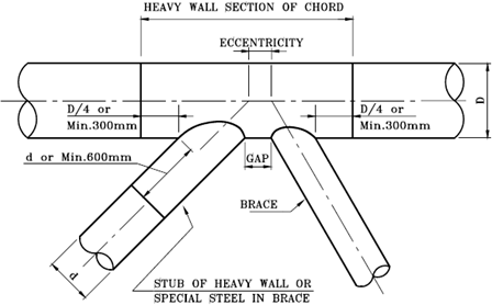
Typical Tubular Joint (Fig 6-1 in N004)
Prior to completing a joint design, the joint should be classified into one of the three categories given by the code. Joint classification is the process whereby a BRACE member connecting into a CHORD member is classified into one of these categories based on the axial force components in the brace. The classification normally considers all the members at a joint that lie in a plane. N-004 defines three joint classification categories: K, X, or Y (or a combination of these).
| Joint Classification | Description |
|---|---|
| K | The axial force in the brace should be balanced by forces in the other braces in the same plane and on the same side of the joint. The code allows a 10% tolerance in the balancing force. |
| X | The axial force in the brace is reacted as a beam shear in the chord. |
| Y | The axial force in the brace is carried through the chord to braces in the opposite side. |
The checks for joint capacity are given in Cl. 6.4.3.2 to 6.4.3.6 and STAAD.Pro performs the checks as per these clauses. However, the program does not deal with conical joint transitions and joints with joint cans. The code also specifies checks and limits for the gaps and eccentricity of joints. This implementation will not perform such geometry checks.
The details of the checks done and the methodology will be discussed in the following sections.
D12.B.6.1 Identification and Classification of CHORD and BRACE Members
This is a two step process where the program automatically identifies the CHORD and BRACE members at a joint and perform a default joint check. The input variables used for the initial joint checks will be generated in an external text file. You can then use this text file to edit or modify the input variables and perform a final check as necessary.
The following syntax is used to initiate the joint checking in the engine.
LOAD LIST load_list
PARAMETER 1
CHECK JOINT { node_list | ALL }
Where:
- load_list = a list of load case numbers to be check against
- node_list = the NODE numbers to be checked. Specifying the ALL keyword option will cause the program to perform the joint check at all the nodes.
For each node specified in the CHECK JOINT command, the program automatically separates out all the members at the node into one CHORD member and one or more BRACE members. The section with the biggest diameter is assumed to be the CHORD and all the other members are assumed as BRACE members. If two or more possible CHORD members have the same diameter, the member with the maximum thickness is considered as the CHORD. The angle between the two members should be within the range of 30° and 90° (inclusive).
Once all the CHORD and BRACE members are identified, the program considers every CHORD to BRACE connection as a separate JOINT. The program the automatically creates the joints and initially considers all the joints as joint class Y. The program then performs all the necessary joint checks as detailed in the following sections and produces the design output. The program will also produce an output file called filename_ JOINTS.txt, where "filename" will be the name of the .std file. This format of this text file is explained in D12.B.8 External Geometry File.
You can then edit this text file to set up the necessary design parameters. Once the program finds of the _JOINTS.txt file, it will read in the necessary parameters from this file and perform the subsequent design checks.