D10.B.7 Flexural Design Strength
In the Limit States Design Method, the flexural design strength of a member is determined mainly by the limit state of lateral torsional buckling. Inelastic bending is allowed and the basic measure of flexural capacity is the plastic moment capacity of the section.
The flexural resistance is a function of plastic moment capacity, actual laterally unbraced length, limiting laterally unbraced length, buckling moment and the bending coefficient. The limiting laterally unbraced length Lu and flexural resistance Mr are functions of the section geometry and are calculated as per the procedure of Section 3.3.2 of the NTC.
The purpose of bending coefficient Cb is to account for the influence of the moment gradient on lateral-torsional buckling. This coefficient can be specified by the user through the use of parameter CB or CBy ( D10.B.11 Design Parameters) or may be calculated by the program (according to LRDF USA specification) if CB is specified as 0.0. In the absence of the parameter CB, a default value of 1.0 will be used.
To specify laterally unsupported length, either of the parameters UNL and UNF (see Table 10B.1) can be used.
It is taken into account the reduction of flexural resistance due to slender web according to section 4.5.8 of the NTC
For the sections where the web and flange are slender the LRDF USA specification was used.
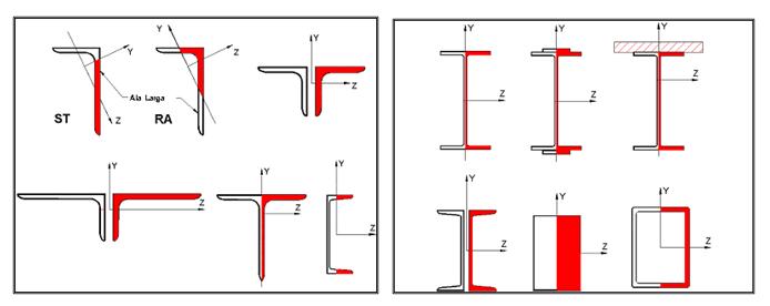
Stress areas due to bending about y axis (MY)

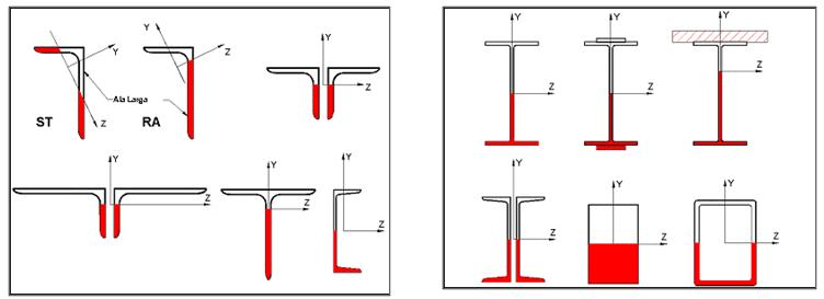
Stress areas due to bending about Z axis (MZ)

