D13.D.3 Beams
Reinforcement areas are calculated for beams of rectangular and T cross section. When calculating the longitudinal reinforcement bending moment about the local axis Z and torsional moments are considered; the influence of longitudinal forces and bending moments in relation to local axis Y is ignored. When calculating transverse reinforcement shear forces parallel to local axis Y and torsional moments are considered.
Reinforcement for beams can be calculated either for strength conditions or from crack width limits using the SSE parameter.
In general, the calculation of reinforcement for beams is carried out two times: once according to strength conditions and again according to crack width limitation. In reinforcement calculations for strength conditions (i.e., the first limit state), design load values must be used. In reinforcement calculations for crack width limitation (i.e., the second limit state), characteristic (i.e., normative or service) load values are used. Using the multiple analysis capability of STAAD.Pro allows you to carry out both calculations in a single analysis and design run.
In most cases, calculation of reinforcement is carried out with only a partial number of load cases. In such cases, the LOAD LIST command is used to indicate the load case numbers. The load case number indicated by the NLT parameter –used to indicate the load cases for permanent and long-term loads– must be included in the list of considered loads.
The parameter BCL can be equal to any value of concrete compression strength class given in SNiP 2.03.01-84*, as well as any intermediate value.
It should be noted that the accuracy of results in calculating transverse reinforcement increases with the value of the NSE parameter.
Parameters SFA and EFA are considered only in the calculation of transverse reinforcement. Beam 1 shown in the following figure has rigid end-links of 0.3m at the start of the beam and 0.2m at the end of the beam. In the STAAD input file, this is modeled as:
MEMBER OFFSET
1 START 0.3 0 0
1 END -0.2 0 0
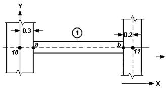
When the MEMBER OFFSET command is used, the forces used in calculation of reinforcement are for a beam whose length is taken from point a to point b (i.e., between the faces of the supporting columns) in the figure. In this case, it is necessary to use the default values of the parameters SFA and EFA (zero).
When the MEMBER OFFSET command not is used, the forces used in calculation of reinforcement are for a beam whose length is taken from node 10 to node 11. In this case, it is necessary to assign the distances to the design parameters SFA and EFA.
CODE RUSSIAN
SFA 0.3 1
EFA 0.2 1
In both cases, the calculated quantity of transverse reinforcement is the same. The calculated quantity of longitudinal reinforcement in the second case will be greater.
For beams, the following output is generated:
- beam number;
- method of calculation (according to conditions of strength or limitations of opened crack width);
- length and cross-sectional dimensions;
- distance from resultant of forces acting in bottom/top reinforcement to bottom/top edge of the section;
- distance from the side edge of cross-section of the beam web to the centroid of longitudinal bars located at this edge;
- concrete class;
- class of longitudinal and transverse reinforcement;
- assumed in calculations bar diameters of longitudinal and transverse reinforcement;
- calculation results of longitudinal and transverse reinforcement (in two tables).
In nine columns of the first table the following results are presented:
- Section – distance of the section from the start of the beam, мм;
- As- – cross-sectional area of longitudinal reinforcement in the bottom zone of cross-section of the beam, if angle BETA=0°, or in the top zone, if BETA=180°, sq.cm;
- As+ – cross-sectional area of longitudinal reinforcement in the top zone of cross-section of the beam , if angle BETA=0°, or in the top zone, if BETA=180°, sq.cm;
- Moments (-/+) – values of bending moments, determining cross-sectional areas of longitudinal reinforcement As* and As* , kNm;
- Load. N. (-/+) – numbers of loading versions, determining cross-sectional areas of longitudinal reinforcement;
- Acrc1 – short-term opened crack width, mm;
- Acrc2 – long-term opened crack width, mm.
Opened crack width is presented only in the case when calculation is performed according to conditions limiting opened crack width.
In ten columns of second table the following results are presented:
- Section – distance of the section from the start of the beam, mm;
- Qsw – intensity of transverse reinforcement, kN/m;
- Asw – cross-sectional area of transverse bars, sq.cm, if their step is 10, 15, 20, 25 or 30 cm;
- Q – value of shear force parallel to the local axis, kN;
- T – value of torsional moment, kNm;
- Load N. – number of loading version, determining intensity of transverse reinforcement.