EX. UK-29 Time History Analysis of a Frame for Seismic Loads
Analysis and design of a structure for seismic loads is demonstrated in this example. In this model, static load cases are solved along with the seismic load case. For the seismic case, the maximum values of displacements, forces and reactions are obtained. The results of the dynamic case are combined with those of the static cases and steel design is performed on the combined cases.
This problem is installed with the program by default to C:\Users\Public\Public Documents\STAAD.Pro CONNECT Edition\Samples\Sample Models\UK\UK-29 Time History Analysis of a Frame for Seismic Loads.std when you install the program.
Actual input is shown in bold lettering followed by explanation.
STAAD SPACE DYNAMIC ANALYSIS FOR SEISMIC LOADS
Every STAAD input file has to begin with the word STAAD. The word SPACE signifies that the structure is a space frame and the geometry is defined through X, Y and Z axes. The remainder of the words form a title to identify this project.
UNIT METER KNS
The units for the data that follows are specified above.
JOINT COORDINATES
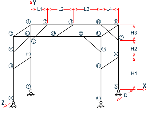
1 0 0 0 ; 2 0 3.5 0 ; 3 0 5.3 0 ; 4 0 7 0
REPEAT ALL 1 9.5 0 0
REPEAT ALL 1 0 0 3
17 1.8 7 0 ; 18 4.6 7 0 ; 19 7.6 7 0
REPEAT ALL 1 0 0 3
For joints 1 through 4, the joint number is followed by the X, Y and Z coordinates as specified above. The coordinates of these joints are used as a basis for generating 12 more joints by incrementing the X & Z coordinates by specific amounts. REPEAT ALL commands are used for the generation. Details of these commands are available in TR.11 ジョイント座標の設定. Following this, another round of explicit definition (joints 17, 18 & 19) and generation (20, 21 & 22) is carried out. The results of the generation may be visually verified using graphical view features in STAAD.Pro.
    MEMBER INCIDENCES
    1 1 2 3
    REPEAT 1 3 4
    7 9 10 9
    10 13 14 12
    13 4 17; 14 17 18; 15 18 19; 16 19 8
    17 12 20; 18 20 21; 19 21 22; 20 22 16
    21 2 10; 22 4 12; 23 6 14
    24 8 16; 25 3 17; 26 7 19; 27 11 20; 28 15 22; 29 18 21
A mixture of explicit definition and generation of member connectivity data (joint numbers between which members are connected) is used to generate 29 members for the structure.
    START GROUP DEFINITION
    MEMBER
    _VERTICAL 1 TO 12
    _XBEAM 13 TO 20
    _ZBEAM 21 TO 24 29
    _BRACE 25 TO 28
    END GROUP DEFINITION
The above block of data is referred to as formation of groups. Group names are a mechanism by which a single moniker can be used to refer to a cluster of entities, such as members. For our structure, the columns are being grouped to a name called VERTICAL, the beams running along the X direction are assigned the name XBEAM, and so on.
    MEMBER PROPERTIES CANADIAN
    _VERTICAL TA ST W310X97
    _XBEAM TA ST W250X39
    _ZBEAM TA ST C200X17
    _BRACE TA ST L152X152X13
Member properties are assigned from the Canadian steel table. The members which receive these properties are those embedded within the respective group names. The benefit of using the group name is apparent here. Just from the looks of the command, we can understand that the diagonal braces are being assigned a single angle. The alternative, which would be
25 TO 28 TA ST L152X152X13
would have required us to go to the graphical tools to get a sense of what members 25 to 28 are.
    UNIT KNS MMS
    DEFINE MATERIAL START
    ISOTROPIC STEEL
    E 200
    POISSON 0.3
    DENSITY 7.8e-008
    ALPHA 6e-006
    DAMP 0.03
    TYPE STEEL
    STRENGTH FY 0.24821 FU 0.399894 RY 1.5 RT 1.2
    END DEFINE MATERIAL
    CONSTANTS
    MATERIAL STEEL ALL
    BETA 180 MEMB 21 22
The DEFINE MATERIAL command is used to specify material properties and the CONSTANT is used to assign the material to all members. The BETA angle for the channels along the left edge is set to 180 so their legs point toward the interior of the structure.
    SUPPORTS
    1 5 9 13 PINNED
The bottom ends of the columns of the platform are pinned supported.
CUT OFF MODE SHAPE 30
The above command is a critical command if you want to override the default number of modes computed and used in a dynamic analysis. The default, which is 6, may not always be sufficient to capture a significant portion of the structural response in a response spectrum or time history analysis, and hence the need to override the default. This command is explained in TR.30.1 打ち切り振動数、モード形状、または時間.
    UNIT METER
    DEFINE TIME HISTORY
    TYPE 1 ACCELERATION
    READ EQDATA.TXT
    ARRIVAL TIME
    0.0
    DAMPING 0.05
There are two stages in the command specification required for a time-history analysis. The first stage is defined above. Here, the parameters of the earthquake (ground acceleration) are provided.
Each data set is individually identified by the number that follows the TYPE command. In this file, only one data set is defined, which is apparent from the fact that only one TYPE is defined.
The word FORCE that follows the TYPE 1 command signifies that this data set is for a ground acceleration. (If you want to specify a forcing function, the keyword FORCE must be used instead.)
Notice the expression READ EQDATA.TXT. It means that we have chosen to specify the time vs. ground acceleration data in the file called EQDATA.TXT. That file must reside in the same folder as the one in which the data file for this structure resides. As explained in the small examples shown in TR.31.4 時刻歴荷重の定義 , the EQDATA.TXT file is a simple text file containing several pairs of time-acceleration data. A sample portion of that file is as shown below.
    0.0000   0.006300
    0.0200   0.003640
    0.0400   0.000990
    0.0600   0.004280
    0.0800   0.007580
    0.1000   0.010870
While it may not be apparent from the above numbers, it may also be noted that the geological data for the site the building sits on indicate that the above acceleration values are a fraction of "g", the acceleration due to gravity. Thus, for example, at 0.02 seconds, the acceleration is 0.00364 multiplied by 9.806 m/sec2 (or 0.00364 multiplied by 32.2 ft/sec2). Consequently, the burden of informing the program that the values need to be multiplied by "g" is upon us, and we shall do so at a later step.
The arrival time value indicates the relative value of time at which the earthquake begins to act upon the structure. We have chosen 0.0, as there is no other dynamic load on the structure from the relative time standpoint. The modal damping ratio for all the modes is set to 0.05.
    LOAD 1 WEIGHT OF STRUCTURE ACTING STATICALLY
    SELFWEIGHT Y -1.0
The above data describe a static load case. The selfweight of the structure is acting in the negative global Y direction.
    LOAD 2 PLATFORM LEVEL LOAD ACTING STATICALLY FLOOR LOAD
    YRA 6.9 7.1 FLOAD -500
Load case 2 is also a static load case. At the Y=7.0m elevation, our structure has a floor slab. But, it is a non-structural entity which, though capable of carrying the loads acting on itself, is not meant to be an integral part of the framing system. It merely transmits the load to the beam-column grid.
There are uniform area loads on the floor (think of the load as wooden pallets supporting boxes of paper). Since the slab is not part of the structural model, how do we tell the program to transmit the imposed load from the slab to the beams without manually converting them to distributed beam loads ourselves? That is where the floor load utility comes in handy. It is a facility where we specify the load as a pressure, and the program converts the pressure to individual beam loads. Thus, the input required is very simple - load intensity in the form of pressure, and the region of the structure in terms of X, Y and Z coordinates in space, of the area over which the pressure acts.
In the process of converting the pressure to beam loads, STAAD will consider the empty space between criss-crossing beams (in plan view) to be panels, similar to the squares of a chess board. The load on each panel is then transferred to beams surrounding the panel, using a triangular or trapezoidal load distribution method.
    LOAD 3 DYNAMIC LOAD
    * MASSES
    SELFWEIGHT X 1.0
    SELFWEIGHT Y 1.0
    SELFWEIGHT Z 1.0
    FLOOR LOAD
    YRANGE 6.9 7.1 FLOAD 500 GX
    YRANGE 6.9 7.1 FLOAD 500 GY
    YRANGE 6.9 7.1 FLOAD 500 GZ
Load case 3 is the dynamic load case, the one which contains the second part of the instruction set for a dynamic analysis to be performed. The data here are
-
loads which will yield the mass values which will populate the mass matrix
-
the directions of the loads, which will yield the degree of freedom numbers of the mass matrix for being populated.
Thus, the selfweight, as well as the imposed loads on the non-structural slab are to be considered as participating in the vibration along all the global directions.
GROUND MOTION X 1 1 9.806
The above command too is part of load case 3. Here we say that the seismic force, whose characteristics are defined by the TYPE 1 time history input data, acting at arrival time 1, is to be applied along the X direction. We mentioned earlier that the acceleration input data was specified as a fraction of g. The number 9.806 indicates the value which the acceleration data, as read from EQDATA.TXT are to be factored by before they are used.
    LOAD COMBINATION 11 (STATIC + POSITIVE OF DYNAMIC)
    1 1.0 2 1.0 3 1.0
    LOAD COMBINATION 12 (STATIC + NEGATIVE OF DYNAMIC)
    1 1.0 2 1.0 3 -1.0
In a time history analysis, the member forces FX thru MZ each have a value for every time step. If there are a 1000 time steps, there will be 1000 values of FX, 1000 for FY etc. for that load case. Not all of them can be used in a further calculation like a steel or concrete design. However, the maximum from among those time steps is available. If we want to do a design, one way to make sure that the structure is not under-designed is to create 2 load combination cases involving the dynamic case, a positive combination, and a negative combination.
That is what is being done above. Load combination case no. 11 consists of the sum of the static load cases (1 & 2) with the positive direction of the dynamic load case (3). Load combination case no. 12 consists of the sum of the static load cases (1 & 2) with the negative direction of the dynamic load case (3). The user has discretion on what load factors to use with these combinations. We have chosen the factors to be 1.0.
PERFORM ANALYSIS
The above is the instruction to perform the analysis related calculations. That means, computing nodal displacements, support reactions, etc.
PRINT ANALYSIS RESULTS
The above command is an instruction to the program to produce a report of the joint displacements, support reactions and member end forces in the output file. As mentioned earlier, for the dynamic case, these will be just the maximum values, not the ones generated for every time step. If you want to see the results for each time step, you may do so by using STAAD's Post-processing facilities.
    LOAD LIST 11 12
    PARAMETER
    CODE CANADIAN
    CHECK CODE ALL
A steel design code check is done according to the Canadian code for load cases 11 and 12.
FINISH
Input File
STAAD SPACE DYNAMIC ANALYSIS FOR SEISMIC LOADS
UNIT METER KNS
JOINT COORDINATES
1 0 0 0 ; 2 0 3.5 0 ; 3 0 5.3 0 ; 4 0 7 0
REPEAT ALL 1 9.5 0 0
REPEAT ALL 1 0 0 3
17 1.8 7 0 ; 18 4.6 7 0 ; 19 7.6 7 0
REPEAT ALL 1 0 0 3
MEMBER INCIDENCES
1 1 2 3
REPEAT 1 3 4
7 9 10 9
10 13 14 12
13 4 17; 14 17 18; 15 18 19; 16 19 8
17 12 20; 18 20 21; 19 21 22; 20 22 16
21 2 10; 22 4 12; 23 6 14
24 8 16; 25 3 17; 26 7 19; 27 11 20; 28 15 22; 29 18 21
START GROUP DEFINITION
MEMBER
_VERTICAL 1 TO 12
_XBEAM 13 TO 20
_ZBEAM 21 TO 24 29
_BRACE 25 TO 28
END GROUP DEFINITION
MEMBER PROPERTIES CANADIAN
_VERTICAL TA ST W310X97
_XBEAM TA ST W250X39
_ZBEAM TA ST C200X17
_BRACE TA ST L152X152X13
UNIT KNS MMS
DEFINE MATERIAL START
ISOTROPIC STEEL
E 200
POISSON 0.3
DENSITY 7.8e-008
ALPHA 6e-006
DAMP 0.03
TYPE STEEL
STRENGTH FY 0.24821 FU 0.399894 RY 1.5 RT 1.2
END DEFINE MATERIAL
CONSTANTS
MATERIAL STEEL ALL
BETA 180 MEMB 21 22
SUPPORTS
1 5 9 13 PINNED
CUT OFF MODE SHAPE 30
UNIT KGS METER
DEFINE TIME HISTORY
TYPE 1 ACCELERATION
READ EQDATA.TXT
ARRIVAL TIME
0.0
DAMPING 0.05
LOAD 1 WEIGHT OF STRUCTURE ACTING STATICALLY
SELFWEIGHT Y -1.0
LOAD 2 PLATFORM LEVEL LOAD ACTING STATICALLY
FLOOR LOAD
YRA 6.9 7.1 FLOAD -500
LOAD 3 DYNAMIC LOAD
* MASSES
SELFWEIGHT X 1.0
SELFWEIGHT Y 1.0
SELFWEIGHT Z 1.0
FLOOR LOAD
YRANGE 6.9 7.1 FLOAD 500 GX
YRANGE 6.9 7.1 FLOAD 500 GY
YRANGE 6.9 7.1 FLOAD 500 GZ
GROUND MOTION X 1 1 9.806
LOAD COMBINATION 11 (STATIC + POSITIVE OF DYNAMIC)
1 1.0 2 1.0 3 1.0
LOAD COMBINATION 12 (STATIC + NEGATIVE OF DYNAMIC)
1 1.0 2 1.0 3 -1.0
PERFORM ANALYSIS
PRINT ANALYSIS RESULTS
LOAD LIST 11 12
PARAMETER
CODE CANADA
CHECK CODE ALL
FINISH
STAAD Output File
PAGE NO. 1 **************************************************** * * * STAAD.Pro CONNECT Edition * * Version 22.07.00.** * * Proprietary Program of * * Bentley Systems, Inc. * * Date= APR 19, 2021 * * Time= 17:27:14 * * * * Licensed to: Bentley Systems Inc * **************************************************** 1. STAAD SPACE DYNAMIC ANALYSIS FOR SEISMIC LOADS INPUT FILE: UK-29 Time History Analysis of a Frame for Seismic Loads.STD 2. UNIT METER KNS 3. JOINT COORDINATES 4. 1 0 0 0 ; 2 0 3.5 0 ; 3 0 5.3 0 ; 4 0 7 0 5. REPEAT ALL 1 9.5 0 0 6. REPEAT ALL 1 0 0 3 7. 17 1.8 7 0 ; 18 4.6 7 0 ; 19 7.6 7 0 8. REPEAT ALL 1 0 0 3 9. MEMBER INCIDENCES 10. 1 1 2 3 11. REPEAT 1 3 4 12. 7 9 10 9 13. 10 13 14 12 14. 13 4 17; 14 17 18; 15 18 19; 16 19 8 15. 17 12 20; 18 20 21; 19 21 22; 20 22 16 16. 21 2 10; 22 4 12; 23 6 14 17. 24 8 16; 25 3 17; 26 7 19; 27 11 20; 28 15 22; 29 18 21 18. START GROUP DEFINITION 19. MEMBER 20. _VERTICAL 1 TO 12 21. _XBEAM 13 TO 20 22. _ZBEAM 21 TO 24 29 23. _BRACE 25 TO 28 24. END GROUP DEFINITION 25. MEMBER PROPERTIES CANADIAN 26. _VERTICAL TA ST W310X97 27. _XBEAM TA ST W250X39 28. _ZBEAM TA ST C200X17 29. _BRACE TA ST L152X152X13 30. UNIT KNS MMS 31. DEFINE MATERIAL START 32. ISOTROPIC STEEL 33. E 200 34. POISSON 0.3 35. DENSITY 7.8E-008 36. ALPHA 6E-006 37. DAMP 0.03 38. TYPE STEEL DYNAMIC ANALYSIS FOR SEISMIC LOADS -- PAGE NO. 2 39. STRENGTH FY 0.24821 FU 0.399894 RY 1.5 RT 1.2 40. END DEFINE MATERIAL 41. CONSTANTS 42. MATERIAL STEEL ALL 43. BETA 180 MEMB 21 22 44. SUPPORTS 45. 1 5 9 13 PINNED 46. CUT OFF MODE SHAPE 30 47. UNIT KGS METER 48. DEFINE TIME HISTORY 49. TYPE 1 ACCELERATION 50. READ EQDATA.TXT 51. ARRIVAL TIME 52. 0.0 53. DAMPING 0.05 54. LOAD 1 WEIGHT OF STRUCTURE ACTING STATICALLY 55. SELFWEIGHT Y -1.0 56. LOAD 2 PLATFORM LEVEL LOAD ACTING STATICALLY 57. FLOOR LOAD 58. YRA 6.9 7.1 FLOAD -500 **NOTE** about Floor/OneWay Loads/Weights. Please note that depending on the shape of the floor you may have to break up the FLOOR/ONEWAY LOAD into multiple commands. For details please refer to Technical Reference Manual Section 5.32.4.2 Note d and/or "5.32.4.3 Note f. 59. LOAD 3 DYNAMIC LOAD 60. * MASSES 61. SELFWEIGHT X 1.0 62. SELFWEIGHT Y 1.0 63. SELFWEIGHT Z 1.0 64. FLOOR LOAD 65. YRANGE 6.9 7.1 FLOAD 500 GX 66. YRANGE 6.9 7.1 FLOAD 500 GY 67. YRANGE 6.9 7.1 FLOAD 500 GZ 68. GROUND MOTION X 1 1 9.806 69. LOAD COMBINATION 11 (STATIC + POSITIVE OF DYNAMIC) 70. 1 1.0 2 1.0 3 1.0 71. LOAD COMBINATION 12 (STATIC + NEGATIVE OF DYNAMIC) 72. 1 1.0 2 1.0 3 -1.0 73. PERFORM ANALYSIS DYNAMIC ANALYSIS FOR SEISMIC LOADS -- PAGE NO. 3 P R O B L E M S T A T I S T I C S ----------------------------------- NUMBER OF JOINTS 22 NUMBER OF MEMBERS 29 NUMBER OF PLATES 0 NUMBER OF SOLIDS 0 NUMBER OF SURFACES 0 NUMBER OF SUPPORTS 4 Using 64-bit analysis engine. SOLVER USED IS THE IN-CORE ADVANCED MATH SOLVER TOTAL PRIMARY LOAD CASES = 3, TOTAL DEGREES OF FREEDOM = 120 TOTAL LOAD COMBINATION CASES = 2 SO FAR. ***NOTE: MASSES DEFINED UNDER LOAD# 3 WILL FORM THE FINAL MASS MATRIX FOR DYNAMIC ANALYSIS. EIGEN METHOD : SUBSPACE ------------------------- NUMBER OF MODES REQUESTED = 30 NUMBER OF EXISTING MASSES IN THE MODEL = 54 NUMBER OF MODES THAT WILL BE USED = 30 *** EIGENSOLUTION : ADVANCED METHOD *** DYNAMIC ANALYSIS FOR SEISMIC LOADS -- PAGE NO. 4 CALCULATED FREQUENCIES FOR LOAD CASE 3 MODE FREQUENCY(CYCLES/SEC) PERIOD(SEC) 1 0.693 1.44295 2 1.215 0.82296 3 1.365 0.73265 4 1.561 0.64059 5 2.077 0.48142 6 3.044 0.32846 7 4.217 0.23712 8 4.273 0.23404 9 5.538 0.18058 10 5.543 0.18039 11 5.728 0.17457 12 12.732 0.07854 13 12.741 0.07849 14 15.103 0.06621 15 15.160 0.06596 16 16.354 0.06115 17 16.361 0.06112 18 45.292 0.02208 19 45.315 0.02207 20 48.670 0.02055 21 48.698 0.02053 22 51.820 0.01930 23 51.966 0.01924 24 54.942 0.01820 25 55.877 0.01790 26 55.892 0.01789 27 65.315 0.01531 28 65.477 0.01527 29 87.675 0.01141 30 87.698 0.01140 MODAL WEIGHT (MODAL MASS TIMES g) IN KGS GENERALIZED MODE X Y Z WEIGHT 1 5.696199E-16 8.610521E-17 1.501941E+04 8.845560E+03 2 1.725302E+04 4.369970E-02 9.060492E-16 1.677679E+04 3 1.246259E-10 2.227836E-15 8.419909E-01 1.266359E+04 4 3.797538E-11 5.527408E-15 4.822830E+00 2.596549E+04 5 2.264965E-15 5.671095E-19 2.366926E+03 6.440201E+03 6 7.725612E-29 4.581123E-28 2.205825E-13 5.200768E+03 7 1.360408E-28 1.189335E-28 1.248163E-12 4.804402E+03 8 1.263752E-15 6.794937E-16 1.923308E+00 8.821168E+03 9 6.201199E-03 9.100304E+03 3.202427E-10 6.018106E+03 10 9.267953E-12 1.303676E-05 2.331645E-01 6.033808E+03 11 1.122349E-16 3.371848E-11 4.085088E+01 8.734126E+03 12 3.013838E+02 4.352954E+01 7.992639E-13 6.235664E+03 DYNAMIC ANALYSIS FOR SEISMIC LOADS -- PAGE NO. 5 13 2.777320E-07 3.953387E-08 8.607835E-04 6.238358E+03 14 2.007435E-17 6.477800E-15 6.997098E+01 8.386677E+02 15 1.351152E-15 5.574236E-14 9.354547E+01 8.424974E+02 16 5.267608E+00 1.221315E+03 1.217787E-10 5.514569E+03 17 1.120384E-08 2.609140E-06 5.604504E-02 5.516366E+03 18 2.828040E-01 1.883040E+03 1.456748E-15 1.675733E+03 19 5.312374E-11 3.531607E-07 7.850585E-06 1.675903E+03 20 4.118067E+01 1.211323E+01 7.491389E-18 1.390503E+03 21 2.318913E-09 7.360545E-10 1.550643E-07 1.389647E+03 22 4.592213E-28 2.466068E-24 3.649706E-17 4.245108E+02 23 7.105320E-27 1.029941E-22 3.767168E-17 4.220495E+02 24 3.105606E-26 2.363414E-24 2.528118E-22 4.868892E+03 25 8.054642E-03 3.932247E+02 4.477776E-14 5.355524E+03 26 6.758715E-12 3.570708E-07 4.932334E-05 5.335615E+03 27 3.325115E-19 2.187351E-15 2.044529E+00 5.603039E+02 28 3.027910E-18 2.830325E-15 2.037832E+00 5.570734E+02 29 7.267861E-01 1.713536E+03 6.998440E-15 2.807387E+03 30 3.470296E-19 9.995084E-16 9.362355E-17 1.982699E+03 DYNAMIC ANALYSIS FOR SEISMIC LOADS -- PAGE NO. 6 MASS PARTICIPATION FACTORS MASS PARTICIPATION FACTORS IN PERCENT -------------------------------------- MODE X Y Z SUMM-X SUMM-Y SUMM-Z 1 0.00 0.00 85.32 0.000 0.000 85.325 2 98.01 0.00 0.00 98.014 0.000 85.325 3 0.00 0.00 0.00 98.014 0.000 85.329 4 0.00 0.00 0.03 98.014 0.000 85.357 5 0.00 0.00 13.45 98.014 0.000 98.803 6 0.00 0.00 0.00 98.014 0.000 98.803 7 0.00 0.00 0.00 98.014 0.000 98.803 8 0.00 0.00 0.01 98.014 0.000 98.814 9 0.00 51.70 0.00 98.014 51.699 98.814 10 0.00 0.00 0.00 98.014 51.699 98.815 11 0.00 0.00 0.23 98.014 51.699 99.047 12 1.71 0.25 0.00 99.726 51.946 99.047 13 0.00 0.00 0.00 99.726 51.946 99.047 14 0.00 0.00 0.40 99.726 51.946 99.445 15 0.00 0.00 0.53 99.726 51.946 99.976 16 0.03 6.94 0.00 99.756 58.884 99.976 17 0.00 0.00 0.00 99.756 58.884 99.977 18 0.00 10.70 0.00 99.757 69.582 99.977 19 0.00 0.00 0.00 99.757 69.582 99.977 20 0.23 0.07 0.00 99.991 69.650 99.977 21 0.00 0.00 0.00 99.991 69.650 99.977 22 0.00 0.00 0.00 99.991 69.650 99.977 23 0.00 0.00 0.00 99.991 69.650 99.977 24 0.00 0.00 0.00 99.991 69.650 99.977 25 0.00 2.23 0.00 99.991 71.884 99.977 26 0.00 0.00 0.00 99.991 71.884 99.977 27 0.00 0.00 0.01 99.991 71.884 99.988 28 0.00 0.00 0.01 99.991 71.884 100.000 29 0.00 9.73 0.00 99.995 81.619 100.000 30 0.00 0.00 0.00 99.995 81.619 100.000 A C T U A L MODAL D A M P I N G USED IN ANALYSIS MODE DAMPING 1 0.05000000 2 0.05000000 3 0.05000000 4 0.05000000 5 0.05000000 6 0.05000000 7 0.05000000 8 0.05000000 9 0.05000000 10 0.05000000 11 0.05000000 12 0.05000000 13 0.05000000 14 0.05000000 15 0.05000000 16 0.05000000 DYNAMIC ANALYSIS FOR SEISMIC LOADS -- PAGE NO. 7 MODE DAMPING 17 0.05000000 18 0.05000000 19 0.05000000 20 0.05000000 21 0.05000000 22 0.05000000 23 0.05000000 24 0.05000000 25 0.05000000 26 0.05000000 27 0.05000000 28 0.05000000 29 0.05000000 30 0.05000000 TIME STEP USED IN TIME HISTORY ANALYSIS = 0.00139 SECONDS NUMBER OF MODES WHOSE CONTRIBUTION IS CONSIDERED = 30 TIME DURATION OF TIME HISTORY ANALYSIS = 31.160 SECONDS NUMBER OF TIME STEPS IN THE SOLUTION PROCESS = 22435 74. PRINT ANALYSIS RESULTS BASE SHEAR UNITS ARE -- KGS METE MAXIMUM BASE SHEAR X= -9.498282E+03 Y= -5.285205E+01 Z= 8.791281E-06 AT TIMES 5.809722 2.445833 2.765278 ANALYSIS RESULTS DYNAMIC ANALYSIS FOR SEISMIC LOADS -- PAGE NO. 8 JOINT DISPLACEMENT (CM RADIANS) STRUCTURE TYPE = SPACE ------------------ JOINT LOAD X-TRANS Y-TRANS Z-TRANS X-ROTAN Y-ROTAN Z-ROTAN 1 1 0.0000 0.0000 0.0000 -0.0000 -0.0000 0.0001 2 0.0000 0.0000 0.0000 0.0000 -0.0000 0.0015 3 0.0000 0.0000 0.0000 0.0000 -0.0000 -0.0173 11 0.0000 0.0000 0.0000 0.0000 -0.0000 -0.0157 12 0.0000 0.0000 0.0000 0.0000 -0.0000 0.0190 2 1 -0.0290 -0.0012 -0.0000 0.0000 -0.0000 0.0000 2 -0.4146 -0.0050 -0.0004 -0.0001 -0.0000 0.0004 3 5.7319 0.0046 0.0000 0.0000 -0.0000 -0.0142 11 5.2883 -0.0015 -0.0005 -0.0001 -0.0000 -0.0138 12 -6.1755 -0.0108 -0.0005 -0.0001 -0.0000 0.0145 3 1 -0.0249 -0.0016 -0.0002 -0.0000 -0.0000 -0.0001 2 -0.3581 -0.0075 -0.0122 -0.0000 -0.0001 -0.0012 3 7.9529 0.0070 0.0000 0.0000 -0.0000 -0.0101 11 7.5699 -0.0021 -0.0124 -0.0000 -0.0001 -0.0113 12 -8.3358 -0.0161 -0.0124 -0.0000 -0.0001 0.0088 4 1 -0.0030 -0.0016 0.0000 0.0000 -0.0000 -0.0001 2 -0.0451 -0.0076 0.0004 0.0002 -0.0000 -0.0020 3 9.3683 0.0023 0.0000 0.0000 0.0000 -0.0083 11 9.3201 -0.0069 0.0004 0.0002 -0.0000 -0.0104 12 -9.4164 -0.0115 0.0004 0.0002 -0.0000 0.0062 5 1 0.0000 0.0000 0.0000 -0.0000 0.0000 -0.0001 2 0.0000 0.0000 0.0000 0.0000 0.0000 -0.0014 3 0.0000 0.0000 0.0000 -0.0000 -0.0000 -0.0174 11 0.0000 0.0000 0.0000 0.0000 0.0000 -0.0189 12 0.0000 0.0000 0.0000 0.0000 0.0000 0.0159 6 1 0.0261 -0.0012 -0.0000 0.0000 0.0000 -0.0000 2 0.3723 -0.0050 -0.0004 -0.0001 0.0000 -0.0002 3 5.7484 -0.0046 -0.0000 -0.0000 -0.0000 -0.0142 11 6.1468 -0.0108 -0.0005 -0.0001 0.0000 -0.0144 12 -5.3500 -0.0015 -0.0005 -0.0001 0.0000 0.0139 7 1 0.0206 -0.0016 -0.0002 -0.0000 0.0000 0.0001 2 0.2940 -0.0075 -0.0122 -0.0000 0.0001 0.0013 3 7.9667 -0.0070 -0.0000 -0.0000 -0.0000 -0.0100 11 8.2813 -0.0161 -0.0124 -0.0000 0.0001 -0.0086 12 -7.6521 -0.0021 -0.0124 -0.0000 0.0001 0.0114 8 1 -0.0027 -0.0016 0.0000 0.0000 0.0000 0.0001 2 -0.0398 -0.0077 0.0004 0.0002 0.0000 0.0021 3 9.3696 -0.0026 -0.0000 -0.0000 0.0000 -0.0082 11 9.3271 -0.0119 0.0004 0.0002 0.0000 -0.0060 12 -9.4121 -0.0068 0.0004 0.0002 0.0000 0.0105 9 1 0.0000 0.0000 0.0000 0.0000 0.0000 0.0001 2 0.0000 0.0000 0.0000 -0.0000 0.0000 0.0015 3 0.0000 0.0000 0.0000 0.0000 -0.0000 -0.0173 11 0.0000 0.0000 0.0000 -0.0000 0.0000 -0.0157 12 0.0000 0.0000 0.0000 -0.0000 0.0000 0.0190 10 1 -0.0290 -0.0012 0.0000 -0.0000 0.0000 0.0000 DYNAMIC ANALYSIS FOR SEISMIC LOADS -- PAGE NO. 9 JOINT DISPLACEMENT (CM RADIANS) STRUCTURE TYPE = SPACE ------------------ JOINT LOAD X-TRANS Y-TRANS Z-TRANS X-ROTAN Y-ROTAN Z-ROTAN 2 -0.4146 -0.0050 0.0004 0.0001 0.0000 0.0004 3 5.7319 0.0046 0.0000 0.0000 -0.0000 -0.0142 11 5.2883 -0.0015 0.0005 0.0001 0.0000 -0.0138 12 -6.1755 -0.0108 0.0005 0.0001 0.0000 0.0145 11 1 -0.0249 -0.0016 0.0002 0.0000 0.0000 -0.0001 2 -0.3581 -0.0075 0.0122 0.0000 0.0001 -0.0012 3 7.9529 0.0070 0.0000 0.0000 -0.0000 -0.0101 11 7.5699 -0.0021 0.0124 0.0000 0.0001 -0.0113 12 -8.3358 -0.0161 0.0124 0.0000 0.0001 0.0088 12 1 -0.0030 -0.0016 -0.0000 -0.0000 0.0000 -0.0001 2 -0.0451 -0.0076 -0.0004 -0.0002 0.0000 -0.0020 3 9.3683 0.0023 0.0000 0.0000 0.0000 -0.0083 11 9.3201 -0.0069 -0.0004 -0.0002 0.0000 -0.0104 12 -9.4164 -0.0115 -0.0004 -0.0002 0.0000 0.0062 13 1 0.0000 0.0000 0.0000 0.0000 -0.0000 -0.0001 2 0.0000 0.0000 0.0000 -0.0000 -0.0000 -0.0014 3 0.0000 0.0000 0.0000 -0.0000 -0.0000 -0.0174 11 0.0000 0.0000 0.0000 -0.0000 -0.0000 -0.0189 12 0.0000 0.0000 0.0000 -0.0000 -0.0000 0.0159 14 1 0.0261 -0.0012 0.0000 -0.0000 -0.0000 -0.0000 2 0.3723 -0.0050 0.0004 0.0001 -0.0000 -0.0002 3 5.7484 -0.0046 -0.0000 -0.0000 -0.0000 -0.0142 11 6.1468 -0.0108 0.0005 0.0001 -0.0000 -0.0144 12 -5.3500 -0.0015 0.0005 0.0001 -0.0000 0.0139 15 1 0.0206 -0.0016 0.0002 0.0000 -0.0000 0.0001 2 0.2940 -0.0075 0.0122 0.0000 -0.0001 0.0013 3 7.9667 -0.0070 -0.0000 -0.0000 -0.0000 -0.0100 11 8.2813 -0.0161 0.0124 0.0000 -0.0001 -0.0086 12 -7.6521 -0.0021 0.0124 0.0000 -0.0001 0.0114 16 1 -0.0027 -0.0016 -0.0000 -0.0000 -0.0000 0.0001 2 -0.0398 -0.0077 -0.0004 -0.0002 -0.0000 0.0021 3 9.3696 -0.0026 -0.0000 -0.0000 0.0000 -0.0082 11 9.3271 -0.0119 -0.0004 -0.0002 -0.0000 -0.0060 12 -9.4121 -0.0068 -0.0004 -0.0002 -0.0000 0.0105 17 1 -0.0027 -0.0267 0.0000 0.0000 0.0000 -0.0002 2 -0.0400 -0.3687 0.0008 0.0001 0.0000 -0.0025 3 9.3513 -1.4019 0.0000 -0.0000 0.0000 -0.0033 11 9.3086 -1.7973 0.0008 0.0001 0.0000 -0.0059 12 -9.3941 1.0065 0.0008 0.0001 0.0000 0.0006 18 1 -0.0029 -0.0644 -0.0000 0.0001 0.0000 -0.0000 2 -0.0425 -0.9647 -0.0000 0.0038 0.0000 -0.0003 3 9.3534 -0.0734 0.0000 0.0000 0.0000 0.0086 11 9.3080 -1.1025 -0.0000 0.0039 0.0000 0.0083 12 -9.3987 -0.9557 -0.0000 0.0039 0.0000 -0.0089 19 1 -0.0031 -0.0296 0.0000 0.0000 -0.0000 0.0002 2 -0.0451 -0.4115 0.0009 0.0001 -0.0000 0.0025 DYNAMIC ANALYSIS FOR SEISMIC LOADS -- PAGE NO. 10 JOINT DISPLACEMENT (CM RADIANS) STRUCTURE TYPE = SPACE ------------------ JOINT LOAD X-TRANS Y-TRANS Z-TRANS X-ROTAN Y-ROTAN Z-ROTAN 3 9.3514 1.4648 -0.0000 0.0000 0.0000 -0.0031 11 9.3032 1.0237 0.0009 0.0001 -0.0000 -0.0004 12 -9.3995 -1.9060 0.0009 0.0001 -0.0000 0.0057 20 1 -0.0027 -0.0267 -0.0000 -0.0000 -0.0000 -0.0002 2 -0.0400 -0.3687 -0.0008 -0.0001 -0.0000 -0.0025 3 9.3513 -1.4019 0.0000 -0.0000 0.0000 -0.0033 11 9.3086 -1.7973 -0.0008 -0.0001 -0.0000 -0.0059 12 -9.3941 1.0065 -0.0008 -0.0001 -0.0000 0.0006 21 1 -0.0029 -0.0644 0.0000 -0.0001 -0.0000 -0.0000 2 -0.0425 -0.9647 0.0000 -0.0038 -0.0000 -0.0003 3 9.3534 -0.0734 0.0000 0.0000 0.0000 0.0086 11 9.3080 -1.1025 0.0000 -0.0039 -0.0000 0.0083 12 -9.3987 -0.9557 0.0000 -0.0039 -0.0000 -0.0089 22 1 -0.0031 -0.0296 -0.0000 -0.0000 0.0000 0.0002 2 -0.0451 -0.4115 -0.0009 -0.0001 0.0000 0.0025 3 9.3514 1.4648 -0.0000 0.0000 0.0000 -0.0031 11 9.3032 1.0237 -0.0009 -0.0001 0.0000 -0.0004 12 -9.3995 -1.9060 -0.0009 -0.0001 0.0000 0.0057 DYNAMIC ANALYSIS FOR SEISMIC LOADS -- PAGE NO. 11 SUPPORT REACTIONS -UNIT KGS METE STRUCTURE TYPE = SPACE ----------------- JOINT LOAD FORCE-X FORCE-Y FORCE-Z MOM-X MOM-Y MOM Z 1 1 61.39 1009.30 0.98 0.00 0.00 0.00 2 872.77 3562.50 -19.74 0.00 0.00 0.00 3 -2356.64 -3311.14 -0.00 0.00 0.00 0.00 11 -1422.49 1260.65 -18.76 0.00 0.00 0.00 12 3290.79 7882.94 -18.76 0.00 0.00 0.00 5 1 -61.39 1009.45 0.98 0.00 0.00 0.00 2 -872.77 3562.50 -19.74 0.00 0.00 0.00 3 -2392.50 3308.29 0.00 0.00 0.00 0.00 11 -3326.65 7880.23 -18.76 0.00 0.00 0.00 12 1458.35 1263.66 -18.76 0.00 0.00 0.00 9 1 61.39 1009.30 -0.98 0.00 0.00 0.00 2 872.77 3562.50 19.74 0.00 0.00 0.00 3 -2356.64 -3311.14 -0.00 0.00 0.00 0.00 11 -1422.49 1260.65 18.76 0.00 0.00 0.00 12 3290.79 7882.94 18.76 0.00 0.00 0.00 13 1 -61.39 1009.45 -0.98 0.00 0.00 0.00 2 -872.77 3562.50 19.74 0.00 0.00 0.00 3 -2392.50 3308.29 0.00 0.00 0.00 0.00 11 -3326.65 7880.23 18.76 0.00 0.00 0.00 12 1458.35 1263.66 18.76 0.00 0.00 0.00 DYNAMIC ANALYSIS FOR SEISMIC LOADS -- PAGE NO. 12 MEMBER END FORCES STRUCTURE TYPE = SPACE ----------------- ALL UNITS ARE -- KGS METE (LOCAL ) MEMBER LOAD JT AXIAL SHEAR-Y SHEAR-Z TORSION MOM-Y MOM-Z 1 1 1 1009.30 -61.39 0.98 0.00 0.00 0.00 2 -666.89 61.39 -0.98 0.00 -3.43 -214.85 2 1 3562.50 -872.77 -19.74 0.00 -0.00 0.00 2 -3562.50 872.77 19.74 0.00 69.09 -3054.69 3 1 -3311.14 2356.64 -0.00 0.00 0.00 0.00 2 3311.14 -2356.64 0.00 0.00 0.00 8248.24 11 1 1260.65 1422.49 -18.76 0.00 -0.00 0.00 2 -918.24 -1422.49 18.76 0.00 65.66 4978.71 12 1 7882.94 -3290.79 -18.76 0.00 -0.00 0.00 2 -7540.53 3290.79 18.76 0.00 65.66 -11517.77 2 1 2 641.00 -61.39 5.97 0.01 -9.03 214.85 3 -464.90 61.39 -5.97 -0.01 -1.72 -325.34 2 2 3562.50 -872.77 112.31 0.24 -79.35 3054.69 3 -3562.50 872.77 -112.31 -0.24 -122.82 -4625.67 3 2 -3311.13 2253.63 -0.00 -0.00 0.00 -8248.24 3 3311.13 -2253.63 0.00 0.00 0.00 12304.78 11 2 892.36 1319.48 118.29 0.24 -88.38 -4978.71 3 -716.27 -1319.48 -118.29 -0.24 -124.54 7353.77 12 2 7514.63 -3187.78 118.29 0.24 -88.38 11517.77 3 -7338.53 3187.78 -118.29 -0.24 -124.54 -17255.79 3 1 3 191.68 186.66 5.96 -0.01 1.70 310.00 4 -25.36 -186.66 -5.96 0.01 -11.84 7.31 2 3 41.65 2832.69 111.63 -0.35 122.13 4570.39 4 -41.65 -2832.69 -111.63 0.35 -311.90 245.19 3 3 6886.37 -8900.34 -0.00 -0.00 -0.00 -12336.68 4 -6886.37 8900.34 0.00 0.00 0.00 -2793.95 11 3 7119.69 -5881.00 117.59 -0.36 123.83 -7456.29 4 -6953.38 5881.00 -117.59 0.36 -323.74 -2541.44 12 3 -6653.04 11919.69 117.60 -0.36 123.83 17217.07 4 6819.36 -11919.69 -117.60 0.36 -323.74 3046.45 4 1 5 1009.45 61.39 0.98 0.00 0.00 -0.00 6 -667.04 -61.39 -0.98 0.00 -3.43 214.85 2 5 3562.50 872.77 -19.74 0.00 0.00 -0.00 6 -3562.50 -872.77 19.74 0.00 69.07 3054.69 3 5 3308.29 2392.50 0.00 0.00 0.00 0.00 6 -3308.29 -2392.50 -0.00 0.00 -0.00 8373.75 11 5 7880.23 3326.65 -18.76 0.00 0.00 -0.00 6 -7537.82 -3326.65 18.76 0.00 65.65 11643.29 12 5 1263.66 -1458.35 -18.76 0.00 0.00 -0.00 6 -921.25 1458.35 18.76 0.00 65.65 -5104.22 DYNAMIC ANALYSIS FOR SEISMIC LOADS -- PAGE NO. 13 MEMBER END FORCES STRUCTURE TYPE = SPACE ----------------- ALL UNITS ARE -- KGS METE (LOCAL ) MEMBER LOAD JT AXIAL SHEAR-Y SHEAR-Z TORSION MOM-Y MOM-Z 5 1 6 641.15 61.39 5.97 -0.01 -9.03 -214.85 7 -465.05 -61.39 -5.97 0.01 -1.72 325.34 2 6 3562.50 872.77 112.28 -0.22 -79.33 -3054.69 7 -3562.50 -872.77 -112.28 0.22 -122.76 4625.67 3 6 3308.16 2288.65 0.00 0.00 -0.00 -8373.75 7 -3308.16 -2288.65 -0.00 -0.00 -0.00 12493.31 11 6 7511.81 3222.80 118.25 -0.23 -88.36 -11643.29 7 -7335.71 -3222.80 -118.25 0.23 -124.49 17444.32 12 6 895.48 -1354.49 118.25 -0.23 -88.36 5104.22 7 -719.39 1354.49 -118.25 0.23 -124.49 -7542.31 6 1 7 206.02 -182.87 5.96 0.01 1.71 -308.77 8 -39.71 182.87 -5.96 -0.01 -11.84 -2.12 2 7 257.08 -2789.79 111.63 0.33 122.14 -4566.17 8 -257.08 2789.79 -111.63 -0.33 -311.91 -176.47 3 7 -6533.99 -9068.05 0.00 -0.00 0.00 -12526.19 8 6533.99 9068.05 -0.00 0.00 -0.00 -2889.65 11 7 -6070.89 -12040.72 117.59 0.34 123.84 -17401.13 8 6237.20 12040.72 -117.59 -0.34 -323.75 -3068.23 12 7 6997.09 6095.39 117.59 0.34 123.84 7651.25 8 -6830.78 -6095.39 -117.59 -0.34 -323.75 2711.06 7 1 9 1009.30 -61.39 -0.98 0.00 -0.00 0.00 10 -666.89 61.39 0.98 0.00 3.43 -214.85 2 9 3562.50 -872.77 19.74 0.00 0.00 -0.00 10 -3562.50 872.77 -19.74 0.00 -69.09 -3054.69 3 9 -3311.14 2356.64 -0.00 0.00 0.00 0.00 10 3311.14 -2356.64 0.00 0.00 0.00 8248.24 11 9 1260.65 1422.49 18.76 0.00 0.00 -0.00 10 -918.24 -1422.49 -18.76 0.00 -65.66 4978.71 12 9 7882.94 -3290.79 18.76 0.00 0.00 -0.00 10 -7540.53 3290.79 -18.76 0.00 -65.66 -11517.78 8 1 10 641.00 -61.39 -5.97 -0.01 9.03 214.85 11 -464.90 61.39 5.97 0.01 1.72 -325.34 2 10 3562.50 -872.77 -112.31 -0.24 79.35 3054.69 11 -3562.50 872.77 112.31 0.24 122.82 -4625.67 3 10 -3311.13 2253.63 -0.00 -0.00 0.00 -8248.24 11 3311.13 -2253.63 0.00 0.00 0.00 12304.78 11 10 892.36 1319.48 -118.29 -0.24 88.38 -4978.71 11 -716.27 -1319.48 118.29 0.24 124.54 7353.77 12 10 7514.63 -3187.79 -118.29 -0.24 88.38 11517.78 11 -7338.53 3187.79 118.29 0.24 124.54 -17255.79 9 1 11 191.68 186.66 -5.96 0.01 -1.70 310.00 12 -25.36 -186.66 5.96 -0.01 11.84 7.31 DYNAMIC ANALYSIS FOR SEISMIC LOADS -- PAGE NO. 14 MEMBER END FORCES STRUCTURE TYPE = SPACE ----------------- ALL UNITS ARE -- KGS METE (LOCAL ) MEMBER LOAD JT AXIAL SHEAR-Y SHEAR-Z TORSION MOM-Y MOM-Z 2 11 41.65 2832.69 -111.63 0.35 -122.13 4570.39 12 -41.65 -2832.69 111.63 -0.35 311.90 245.19 3 11 6886.37 -8900.35 -0.00 -0.00 -0.00 -12336.68 12 -6886.37 8900.35 0.00 0.00 0.00 -2793.95 11 11 7119.69 -5881.00 -117.60 0.36 -123.83 -7456.29 12 -6953.38 5881.00 117.60 -0.36 323.74 -2541.45 12 11 -6653.05 11919.69 -117.59 0.36 -123.83 17217.07 12 6819.36 -11919.69 117.59 -0.36 323.74 3046.45 10 1 13 1009.45 61.39 -0.98 0.00 -0.00 -0.00 14 -667.04 -61.39 0.98 0.00 3.43 214.85 2 13 3562.50 872.77 19.74 0.00 0.00 -0.00 14 -3562.50 -872.77 -19.74 0.00 -69.07 3054.69 3 13 3308.29 2392.50 0.00 0.00 0.00 0.00 14 -3308.29 -2392.50 -0.00 0.00 -0.00 8373.75 11 13 7880.23 3326.65 18.76 0.00 0.00 -0.00 14 -7537.82 -3326.65 -18.76 0.00 -65.65 11643.29 12 13 1263.66 -1458.35 18.76 0.00 0.00 -0.00 14 -921.25 1458.35 -18.76 0.00 -65.65 -5104.22 11 1 14 641.15 61.39 -5.97 0.01 9.03 -214.85 15 -465.05 -61.39 5.97 -0.01 1.72 325.34 2 14 3562.50 872.77 -112.28 0.22 79.33 -3054.69 15 -3562.50 -872.77 112.28 -0.22 122.76 4625.67 3 14 3308.16 2288.65 0.00 0.00 -0.00 -8373.75 15 -3308.16 -2288.65 -0.00 -0.00 -0.00 12493.31 11 14 7511.81 3222.80 -118.25 0.23 88.36 -11643.29 15 -7335.71 -3222.80 118.25 -0.23 124.49 17444.32 12 14 895.48 -1354.49 -118.25 0.23 88.36 5104.22 15 -719.39 1354.49 118.25 -0.23 124.49 -7542.31 12 1 15 206.02 -182.87 -5.96 -0.01 -1.71 -308.77 16 -39.71 182.87 5.96 0.01 11.84 -2.12 2 15 257.08 -2789.79 -111.63 -0.33 -122.14 -4566.17 16 -257.08 2789.79 111.63 0.33 311.91 -176.47 3 15 -6533.99 -9068.05 0.00 -0.00 0.00 -12526.20 16 6533.99 9068.05 -0.00 0.00 -0.00 -2889.65 11 15 -6070.89 -12040.72 -117.59 -0.34 -123.84 -17401.14 16 6237.20 12040.72 117.59 0.34 323.75 -3068.23 12 15 6997.09 6095.39 -117.59 -0.34 -123.84 7651.26 16 -6830.78 -6095.39 117.59 0.34 323.75 2711.06 13 1 4 -186.66 -0.53 -0.01 0.00 -0.01 -7.31 17 186.66 70.96 0.01 -0.00 0.03 -57.03 2 4 -2832.69 -520.85 -0.69 0.09 -0.29 -245.19 17 2832.69 1308.35 0.69 -0.09 1.54 -1176.10 DYNAMIC ANALYSIS FOR SEISMIC LOADS -- PAGE NO. 15 MEMBER END FORCES STRUCTURE TYPE = SPACE ----------------- ALL UNITS ARE -- KGS METE (LOCAL ) MEMBER LOAD JT AXIAL SHEAR-Y SHEAR-Z TORSION MOM-Y MOM-Z 3 4 9442.80 6886.14 -0.00 0.00 -0.00 2793.95 17 -9442.80 -6886.14 0.00 -0.00 0.00 9601.10 11 4 6423.46 6364.76 -0.70 0.09 -0.30 2541.44 17 -6423.46 -5506.82 0.70 -0.09 1.57 8367.98 12 4 -12462.15 -7407.52 -0.70 0.09 -0.30 -3046.45 17 12462.15 8265.46 0.70 -0.09 1.57 -10834.23 14 1 17 61.39 129.40 -0.00 -0.03 0.01 67.81 18 -61.39 -19.82 0.00 0.03 -0.01 141.09 2 17 872.77 2212.50 -0.01 -1.76 0.27 1193.12 18 -872.77 -675.00 0.01 1.76 -0.24 2343.13 3 17 -725.43 -3432.33 -0.00 -0.00 -0.00 -10005.50 18 725.43 3432.33 0.00 0.00 -0.00 395.71 11 17 208.72 -1090.44 -0.01 -1.79 0.28 -8744.57 18 -208.72 2737.51 0.01 1.79 -0.24 2879.93 12 17 1659.58 5774.23 -0.01 -1.79 0.28 11266.44 18 -1659.58 -4127.16 0.01 1.79 -0.24 2088.51 15 1 18 61.39 -6.07 0.00 0.03 0.01 -141.09 19 -61.39 123.46 -0.00 -0.03 -0.01 -53.20 2 18 872.77 -450.00 0.01 1.64 0.23 -2343.13 19 -872.77 2137.50 -0.01 -1.64 -0.26 -975.62 3 18 667.43 -3441.37 0.00 -0.00 0.00 -395.71 19 -667.43 3441.37 -0.00 0.00 -0.00 -9929.10 11 18 1601.58 -3897.43 0.01 1.67 0.24 -2879.93 19 -1601.58 5702.33 -0.01 -1.67 -0.27 -10957.92 12 18 266.73 2985.30 0.01 1.67 0.24 -2088.51 19 -266.73 -1180.40 -0.01 -1.67 -0.27 8900.27 16 1 19 -182.87 60.53 0.01 -0.00 -0.03 42.27 8 182.87 13.82 -0.01 0.00 0.01 2.12 2 19 -2789.79 1167.92 0.66 -0.08 -1.52 970.08 8 2789.79 -305.42 -0.66 0.08 0.27 176.47 3 19 -9627.97 6534.44 -0.00 0.00 0.00 9525.79 8 9627.97 -6534.44 0.00 -0.00 -0.00 2889.65 11 19 -12600.64 7762.89 0.67 -0.09 -1.55 10538.13 8 12600.64 -6826.04 -0.67 0.09 0.28 3068.23 12 19 6655.31 -5305.98 0.67 -0.09 -1.55 -8513.44 8 -6655.31 6242.83 -0.67 0.09 0.28 -2711.06 17 1 12 -186.66 -0.53 0.01 -0.00 0.01 -7.31 20 186.66 70.96 -0.01 0.00 -0.03 -57.03 2 12 -2832.69 -520.85 0.69 -0.09 0.29 -245.19 20 2832.69 1308.35 -0.69 0.09 -1.54 -1176.10 3 12 9442.80 6886.14 -0.00 0.00 -0.00 2793.95 20 -9442.80 -6886.14 0.00 -0.00 0.00 9601.11 DYNAMIC ANALYSIS FOR SEISMIC LOADS -- PAGE NO. 16 MEMBER END FORCES STRUCTURE TYPE = SPACE ----------------- ALL UNITS ARE -- KGS METE (LOCAL ) MEMBER LOAD JT AXIAL SHEAR-Y SHEAR-Z TORSION MOM-Y MOM-Z 11 12 6423.46 6364.76 0.70 -0.09 0.30 2541.45 20 -6423.46 -5506.82 -0.70 0.09 -1.57 8367.98 12 12 -12462.15 -7407.52 0.70 -0.09 0.30 -3046.45 20 12462.15 8265.46 -0.70 0.09 -1.57 -10834.23 18 1 20 61.39 129.40 0.00 0.03 -0.01 67.81 21 -61.39 -19.82 -0.00 -0.03 0.01 141.09 2 20 872.77 2212.50 0.01 1.76 -0.27 1193.12 21 -872.77 -675.00 -0.01 -1.76 0.24 2343.13 3 20 -725.43 -3432.34 -0.00 -0.00 -0.00 -10005.50 21 725.43 3432.34 0.00 0.00 -0.00 395.71 11 20 208.72 -1090.44 0.01 1.79 -0.28 -8744.57 21 -208.72 2737.51 -0.01 -1.79 0.24 2879.93 12 20 1659.58 5774.23 0.01 1.79 -0.28 11266.44 21 -1659.58 -4127.16 -0.01 -1.79 0.24 2088.51 19 1 21 61.39 -6.07 -0.00 -0.03 -0.01 -141.09 22 -61.39 123.46 0.00 0.03 0.01 -53.20 2 21 872.77 -450.00 -0.01 -1.64 -0.23 -2343.13 22 -872.77 2137.50 0.01 1.64 0.26 -975.62 3 21 667.43 -3441.37 0.00 -0.00 0.00 -395.71 22 -667.43 3441.37 -0.00 0.00 -0.00 -9929.10 11 21 1601.58 -3897.43 -0.01 -1.67 -0.24 -2879.93 22 -1601.58 5702.33 0.01 1.67 0.27 -10957.92 12 21 266.73 2985.30 -0.01 -1.67 -0.24 -2088.51 22 -266.73 -1180.40 0.01 1.67 0.27 8900.27 20 1 22 -182.87 60.53 -0.01 0.00 0.03 42.27 16 182.87 13.82 0.01 -0.00 -0.01 2.12 2 22 -2789.79 1167.92 -0.66 0.08 1.52 970.08 16 2789.79 -305.42 0.66 -0.08 -0.27 176.47 3 22 -9627.98 6534.44 -0.00 0.00 0.00 9525.79 16 9627.98 -6534.44 0.00 -0.00 -0.00 2889.65 11 22 -12600.64 7762.89 -0.67 0.09 1.55 10538.13 16 12600.64 -6826.04 0.67 -0.09 -0.28 3068.23 12 22 6655.31 -5305.98 -0.67 0.09 1.55 -8513.44 16 -6655.31 6242.84 0.67 -0.09 -0.28 -2711.06 21 1 2 -5.00 -25.89 0.00 -0.00 0.01 -12.46 10 5.00 -25.89 -0.00 0.00 -0.01 12.46 2 2 -132.05 -0.00 0.00 -0.00 0.24 -10.26 10 132.05 0.00 -0.00 0.00 -0.24 10.26 3 2 0.00 0.00 0.00 -0.00 -0.00 0.00 10 0.00 -0.00 -0.00 0.00 -0.00 0.00 11 2 -137.05 -25.89 0.00 -0.00 0.24 -22.72 10 137.05 -25.89 -0.00 0.00 -0.24 22.72 DYNAMIC ANALYSIS FOR SEISMIC LOADS -- PAGE NO. 17 MEMBER END FORCES STRUCTURE TYPE = SPACE ----------------- ALL UNITS ARE -- KGS METE (LOCAL ) MEMBER LOAD JT AXIAL SHEAR-Y SHEAR-Z TORSION MOM-Y MOM-Z 12 2 -137.05 -25.89 -0.00 0.00 0.24 -22.72 10 137.05 -25.89 0.00 -0.00 -0.24 22.72 22 1 4 5.97 -25.89 0.00 -0.00 0.00 -11.85 12 -5.97 -25.89 -0.00 0.00 -0.00 11.85 2 4 112.33 -562.50 0.00 0.00 0.06 -311.99 12 -112.33 -562.50 -0.00 -0.00 -0.06 311.99 3 4 0.00 0.00 0.00 -0.00 -0.00 0.00 12 0.00 -0.00 -0.00 0.00 -0.00 0.00 11 4 118.30 -588.39 0.00 -0.00 0.06 -323.84 12 -118.30 -588.39 -0.00 0.00 -0.06 323.84 12 4 118.30 -588.39 -0.00 0.00 0.06 -323.84 12 -118.30 -588.39 0.00 -0.00 -0.06 323.84 23 1 6 -4.99 25.89 -0.00 -0.00 0.01 12.46 14 4.99 25.89 0.00 0.00 -0.01 -12.46 2 6 -132.01 -0.00 0.00 -0.00 0.22 10.26 14 132.01 0.00 -0.00 0.00 -0.22 -10.26 3 6 0.00 0.00 0.00 -0.00 -0.00 0.00 14 0.00 -0.00 -0.00 0.00 -0.00 0.00 11 6 -137.01 25.89 0.00 -0.00 0.23 22.71 14 137.01 25.89 -0.00 0.00 -0.23 -22.71 12 6 -137.01 25.89 -0.00 0.00 0.23 22.71 14 137.01 25.89 0.00 -0.00 -0.23 -22.71 24 1 8 5.97 25.89 -0.00 -0.00 0.00 11.85 16 -5.97 25.89 0.00 0.00 -0.00 -11.85 2 8 112.29 562.50 -0.00 -0.00 0.06 311.99 16 -112.29 562.50 0.00 0.00 -0.06 -311.99 3 8 0.00 0.00 -0.00 -0.00 0.00 0.00 16 0.00 -0.00 0.00 0.00 0.00 0.00 11 8 118.26 588.39 -0.00 -0.00 0.06 323.84 16 -118.26 588.39 0.00 0.00 -0.06 -323.84 12 8 118.26 588.39 0.00 0.00 0.06 323.84 16 -118.26 588.39 -0.00 -0.00 -0.06 -323.84 25 1 3 367.93 28.33 0.01 -0.00 0.02 15.34 17 -317.90 24.65 -0.01 0.00 -0.05 -10.79 2 3 5111.42 15.45 0.68 -0.10 0.90 55.28 17 -5111.42 -15.45 -0.68 0.10 -2.59 -17.03 3 3 -15037.77 176.23 0.00 0.00 -0.00 31.99 17 15037.77 -176.23 -0.00 -0.00 0.00 404.40 11 3 -9558.42 220.00 0.69 -0.10 0.93 102.61 17 9608.45 -167.03 -0.69 0.10 -2.64 376.59 12 3 20517.12 -132.45 0.69 -0.10 0.93 38.63 17 -20467.09 185.42 -0.69 0.10 -2.64 -432.21 DYNAMIC ANALYSIS FOR SEISMIC LOADS -- PAGE NO. 18 MEMBER END FORCES STRUCTURE TYPE = SPACE ----------------- ALL UNITS ARE -- KGS METE (LOCAL ) MEMBER LOAD JT AXIAL SHEAR-Y SHEAR-Z TORSION MOM-Y MOM-Z 26 1 7 354.75 30.17 -0.01 0.00 -0.02 16.58 19 -304.72 25.75 0.01 -0.00 0.05 -10.94 2 7 4933.53 21.16 -0.65 0.10 -0.83 59.49 19 -4933.53 -21.16 0.65 -0.10 2.48 -5.54 3 7 14950.07 -171.11 -0.00 0.00 0.00 -33.13 19 -14950.07 171.11 0.00 -0.00 0.00 -403.31 11 7 20238.35 -119.78 -0.66 0.10 -0.85 42.93 19 -20188.32 175.70 0.66 -0.10 2.53 -419.79 12 7 -9661.80 222.44 -0.66 0.10 -0.85 109.20 19 9711.83 -166.53 0.66 -0.10 2.53 386.83 27 1 11 367.93 28.33 -0.01 0.00 -0.02 15.34 20 -317.90 24.65 0.01 -0.00 0.05 -10.79 2 11 5111.42 15.45 -0.68 0.10 -0.90 55.28 20 -5111.42 -15.45 0.68 -0.10 2.59 -17.03 3 11 -15037.77 176.23 0.00 0.00 -0.00 31.99 20 15037.77 -176.23 -0.00 -0.00 0.00 404.40 11 11 -9558.42 220.00 -0.69 0.10 -0.93 102.61 20 9608.45 -167.03 0.69 -0.10 2.64 376.59 12 11 20517.12 -132.45 -0.69 0.10 -0.93 38.63 20 -20467.09 185.42 0.69 -0.10 2.64 -432.21 28 1 15 354.75 30.17 0.01 -0.00 0.02 16.58 22 -304.72 25.75 -0.01 0.00 -0.05 -10.94 2 15 4933.53 21.16 0.65 -0.10 0.83 59.49 22 -4933.53 -21.16 -0.65 0.10 -2.48 -5.54 3 15 14950.07 -171.11 -0.00 0.00 0.00 -33.13 22 -14950.07 171.11 0.00 -0.00 0.00 -403.31 11 15 20238.35 -119.78 0.66 -0.10 0.85 42.93 22 -20188.32 175.70 -0.66 0.10 -2.53 -419.79 12 15 -9661.80 222.44 0.66 -0.10 0.85 109.20 22 9711.83 -166.53 -0.66 0.10 -2.53 386.83 29 1 18 -0.00 25.89 -0.00 0.00 0.00 0.06 21 0.00 25.89 0.00 -0.00 -0.00 -0.06 2 18 -0.02 1125.00 -0.00 0.00 0.00 3.41 21 0.02 1125.00 0.00 -0.00 -0.00 -3.41 3 18 0.00 0.00 0.00 0.00 -0.00 0.00 21 0.00 -0.00 -0.00 -0.00 -0.00 0.00 11 18 -0.02 1150.89 0.00 0.00 0.00 3.47 21 0.02 1150.89 -0.00 -0.00 -0.00 -3.47 12 18 -0.02 1150.89 -0.00 -0.00 0.00 3.47 21 0.02 1150.89 0.00 0.00 -0.00 -3.47 DYNAMIC ANALYSIS FOR SEISMIC LOADS -- PAGE NO. 19 ************** END OF LATEST ANALYSIS RESULT ************** 75. LOAD LIST 11 12 76. PARAMETER 77. CODE CANADA 78. CHECK CODE ALL STEEL DESIGN DYNAMIC ANALYSIS FOR SEISMIC LOADS -- PAGE NO. 20 STAAD.PRO CODE CHECKING - S16-14 (v1.0) ******************************************* ALL UNITS ARE - KN MET (UNLESS OTHERWISE Noted) MEMBER TABLE RESULT/ CRITICAL COND/ RATIO/ LOADING/ FX MY MZ LOCATION ======================================================================= 1 ST W310X97 (CANADIAN SECTIONS) PASS Cl. 13.8.3 0.321 12 73.95 C -0.64 112.95 3.50 -------------------- END OF DESIGN OUTPUT OF MEMBER 1 -------------------- 2 ST W310X97 (CANADIAN SECTIONS) PASS Cl. 13.8.3 0.467 12 71.97 C 1.22 169.22 1.80 -------------------- END OF DESIGN OUTPUT OF MEMBER 2 -------------------- 3 ST W310X97 (CANADIAN SECTIONS) PASS Cl. 13.9.1 0.464 12 65.24 T 1.21 168.84 0.00 -------------------- END OF DESIGN OUTPUT OF MEMBER 3 -------------------- 4 ST W310X97 (CANADIAN SECTIONS) PASS Cl. 13.8.3 0.324 11 73.92 C -0.64 -114.18 3.50 -------------------- END OF DESIGN OUTPUT OF MEMBER 4 -------------------- 5 ST W310X97 (CANADIAN SECTIONS) PASS Cl. 13.8.3 0.471 11 71.94 C 1.22 -171.07 1.80 -------------------- END OF DESIGN OUTPUT OF MEMBER 5 -------------------- 6 ST W310X97 (CANADIAN SECTIONS) PASS Cl. 13.9.1 0.467 11 59.54 T 1.21 -170.65 0.00 -------------------- END OF DESIGN OUTPUT OF MEMBER 6 -------------------- 7 ST W310X97 (CANADIAN SECTIONS) PASS Cl. 13.8.3 0.321 12 73.95 C 0.64 112.95 3.50 -------------------- END OF DESIGN OUTPUT OF MEMBER 7 -------------------- DYNAMIC ANALYSIS FOR SEISMIC LOADS -- PAGE NO. 21 8 ST W310X97 (CANADIAN SECTIONS) PASS Cl. 13.8.3 0.467 12 71.97 C -1.22 169.22 1.80 -------------------- END OF DESIGN OUTPUT OF MEMBER 8 -------------------- 9 ST W310X97 (CANADIAN SECTIONS) PASS Cl. 13.9.1 0.464 12 65.24 T -1.21 168.84 0.00 -------------------- END OF DESIGN OUTPUT OF MEMBER 9 -------------------- 10 ST W310X97 (CANADIAN SECTIONS) PASS Cl. 13.8.3 0.324 11 73.92 C 0.64 -114.18 3.50 -------------------- END OF DESIGN OUTPUT OF MEMBER 10 -------------------- 11 ST W310X97 (CANADIAN SECTIONS) PASS Cl. 13.8.3 0.471 11 71.94 C -1.22 -171.07 1.80 -------------------- END OF DESIGN OUTPUT OF MEMBER 11 -------------------- 12 ST W310X97 (CANADIAN SECTIONS) PASS Cl. 13.9.1 0.467 11 59.54 T -1.21 -170.65 0.00 -------------------- END OF DESIGN OUTPUT OF MEMBER 12 -------------------- 13 ST W250X39 (CANADIAN SECTIONS) PASS Cl. 13.9.1 0.864 12 122.21 T -0.02 106.25 1.80 -------------------- END OF DESIGN OUTPUT OF MEMBER 13 -------------------- 14 ST W250X39 (CANADIAN SECTIONS) PASS Cl. 13.8 0.798 12 16.27 C 0.00 110.49 0.00 -------------------- END OF DESIGN OUTPUT OF MEMBER 14 -------------------- 15 ST W250X39 (CANADIAN SECTIONS) PASS Cl. 13.8 0.776 11 15.71 C 0.00 107.46 3.00 -------------------- END OF DESIGN OUTPUT OF MEMBER 15 -------------------- DYNAMIC ANALYSIS FOR SEISMIC LOADS -- PAGE NO. 22 16 ST W250X39 (CANADIAN SECTIONS) PASS Cl. 13.9.1 0.844 11 123.57 T -0.02 103.34 0.00 -------------------- END OF DESIGN OUTPUT OF MEMBER 16 -------------------- 17 ST W250X39 (CANADIAN SECTIONS) PASS Cl. 13.9.1 0.864 12 122.21 T 0.02 106.25 1.80 -------------------- END OF DESIGN OUTPUT OF MEMBER 17 -------------------- 18 ST W250X39 (CANADIAN SECTIONS) PASS Cl. 13.8 0.798 12 16.27 C -0.00 110.49 0.00 -------------------- END OF DESIGN OUTPUT OF MEMBER 18 -------------------- 19 ST W250X39 (CANADIAN SECTIONS) PASS Cl. 13.8 0.776 11 15.71 C -0.00 107.46 3.00 -------------------- END OF DESIGN OUTPUT OF MEMBER 19 -------------------- 20 ST W250X39 (CANADIAN SECTIONS) PASS Cl. 13.9.1 0.844 11 123.57 T 0.02 103.34 0.00 -------------------- END OF DESIGN OUTPUT OF MEMBER 20 -------------------- 21 ST C200X17 (CANADIAN SECTIONS) PASS Cl. 13.9.1 0.009 12 1.34 T 0.00 -0.22 0.00 -------------------- END OF DESIGN OUTPUT OF MEMBER 21 -------------------- 22 ST C200X17 (CANADIAN SECTIONS) PASS Cl. 13.8.3 0.118 11 1.16 C 0.00 -3.18 3.00 -------------------- END OF DESIGN OUTPUT OF MEMBER 22 -------------------- 23 ST C200X17 (CANADIAN SECTIONS) PASS Cl. 13.9.1 0.009 12 1.34 T 0.00 0.22 3.00 -------------------- END OF DESIGN OUTPUT OF MEMBER 23 -------------------- DYNAMIC ANALYSIS FOR SEISMIC LOADS -- PAGE NO. 23 24 ST C200X17 (CANADIAN SECTIONS) PASS Cl. 13.8.3 0.118 11 1.16 C 0.00 3.18 0.00 -------------------- END OF DESIGN OUTPUT OF MEMBER 24 -------------------- 25 ST L152X152X13 (CANADIAN SECTIONS) PASS Cl. 13.8.3 0.632 12 200.71 C -0.03 4.24 2.48 -------------------- END OF DESIGN OUTPUT OF MEMBER 25 -------------------- 26 ST L152X152X13 (CANADIAN SECTIONS) PASS Cl. 13.8.3 0.630 11 197.98 C 0.02 4.12 2.55 -------------------- END OF DESIGN OUTPUT OF MEMBER 26 -------------------- 27 ST L152X152X13 (CANADIAN SECTIONS) PASS Cl. 13.8.3 0.632 12 200.71 C 0.03 4.24 2.48 -------------------- END OF DESIGN OUTPUT OF MEMBER 27 -------------------- 28 ST L152X152X13 (CANADIAN SECTIONS) PASS Cl. 13.8.3 0.630 11 197.98 C -0.02 4.12 2.55 -------------------- END OF DESIGN OUTPUT OF MEMBER 28 -------------------- 29 ST C200X17 (CANADIAN SECTIONS) PASS Cl. 13.8.3 0.444 11 0.00 T 0.00 -11.19 1.50 -------------------- END OF DESIGN OUTPUT OF MEMBER 29 -------------------- ***NOTE:OMEGA1 AND OMEGA2 ARE CALCULATED USING C/S MOMENT OF ANALYTICAL MEMBERS 79. FINISH DYNAMIC ANALYSIS FOR SEISMIC LOADS -- PAGE NO. 24 *********** END OF THE STAAD.Pro RUN *********** **** DATE= APR 19,2021 TIME= 17:27:16 **** ************************************************************ * For technical assistance on STAAD.Pro, please visit * * http://www.bentley.com/en/support/ * * * * Details about additional assistance from * * Bentley and Partners can be found at program menu * * Help->Technical Support * * * * Copyright (c) Bentley Systems, Inc. * * http://www.bentley.com * ************************************************************