EX. UK-9 Modeling Slabs and Shear Walls Using Finite Elements
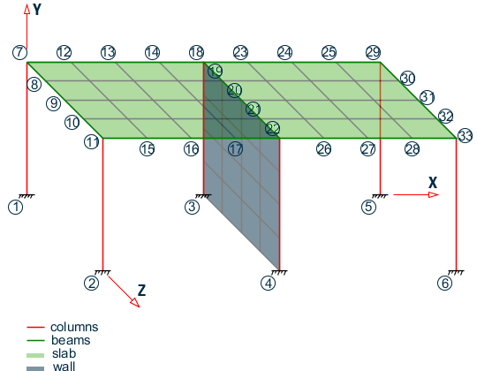
The space frame structure in this example consists of frame members and finite elements (plates). The finite element part is used to model floor slabs and a shear wall. Concrete design of an element is performed.
This problem is installed with the program by default to C:\Users\Public\Public Documents\STAAD.Pro CONNECT Edition\Samples\Sample Models\UK\UK-9 Modeling Slabs and Shear Walls Using Finite Elements.STD when you install the program.
Actual input is shown in bold lettering followed by explanation.
    STAAD SPACE
    * EXAMPLE PROBLEM WITH FRAME MEMBERS AND FINITE ELEMENTS
Every STAAD input file has to begin with the word STAAD. The word SPACE signifies that the structure is a space frame and the geometry is defined through X, Y and Z axes. The second line forms the title to identify this project.
UNIT METER NEWTON
The units for the data that follows are specified above.
    JOINT COORD
    1 0 0 0 ; 2 0 0 6
    REP ALL 2 6 0 0
    7 0 4.5 0 11 0 4.5 6
    12 1.5 4.5 0 14 4.5 4.5 0
    15 1.5 4.5 6 17 4.5 4.5 6
    18 6 4.5 0 22 6 4.5 6
    23 7.5 4.5 0 25 10.5 4.5 0
    26 7.5 4.5 6 28 10.5 4.5 6
    29 12 4.5 0 33 12 4.5 6
    34 6 1.125 0 36 6 3.375 0
    37 6 1.125 6 39 6 3.375 6
The joint numbers and their coordinates are defined through the above set of commands. The automatic generation facility has been used several times in the above lines. See TR.11 ジョイント座標の設定 where the joint coordinate generation facilities are described.
    MEMBER INCI
    *COLUMNS
    1 1 7 ; 2 2 11
    3 3 34 ; 4 34 35 ; 5 35 36 ; 6 36 18
    7 4 37 ; 8 37 38 ; 9 38 39 ; 10 39 22
    11 5 29 ; 12 6 33
    *BEAMS IN Z DIRECTION AT X=0
    13 7 8 16
    *BEAMS IN Z DIRECTION AT X=6.0
    17 18 19 20
    *BEAMS IN Z DIRECTION AT X=12.0
    21 29 30 24
    *BEAMS IN X DIRECTION AT Z = 0
    25 7 12 ; 26 12 13 ; 27 13 14 ; 28 14 18
    29 18 23 ; 30 23 24 ; 31 24 25 ; 32 25 29
    *BEAMS IN X DIRECTION AT Z = 12.0
    33 11 15 ; 34 15 16 ; 35 16 17 ; 36 17 22
    37 22 26 ; 38 26 27 ; 39 27 28 ; 40 28 33
The member incidences are defined through the above set of commands. For some members, the member number followed by the start and end joint numbers are defined. In other cases, STAAD's automatic generation facilities are utilized. Refer to TR.12 メンバー生成の設定 for additional details.
    DEFINE MESH
    A JOINT 7
    B JOINT 11
    C JOINT 22
    D JOINT 18
    E JOINT 33
    F JOINT 29
    G JOINT 3
    H JOINT 4
The above lines define the nodes of super-elements. Super-elements are plate/shell surfaces from which a number of individual plate/shell elements can be generated. In this case, the points describe the outer corners of a slab and that of a shear wall. Our goal is to define the slab and the wall as several plate/shell elements.
    GENERATE ELEMENT
    MESH ABCD 4 4
    MESH DCEF 4 4
    MESH DCHG 4 4
The above lines form the instructions to generate individual 4-noded elements from the super-element profiles. For example, the command MESH ABCD 4 4 means that STAAD.Pro has to generate 16 elements from the surface formed by the points A, B, C and D with 4 elements along the edges AB & CD and 4 elements along the edges BC & DA.
    UNIT MMS
    MEMB PROP
    1 TO 40 PRIS YD 300 ZD 300
Members 1 to 40 are defined as a rectangular prismatic section with 300 mm depth and 300 mm width.
    ELEM PROP
    41 TO 88 TH 150
Elements 41 to 88 are defined to be 150 mm thick.
    DEFINE MATERIAL START
    ISOTROPIC CONCRETE
    E 21.0
    POISSON 0.17
    DENSITY 2.36158e-008
    ALPHA 5e-006
    DAMP 0.05
    G 9.25
    TYPE CONCRETE
    STRENGTH FCU 0.0275
    END DEFINE MATERIAL
    CONSTANTS
    MATERIAL CONCRETE ALL
The DEFINE MATERIAL command is used to specify material properties and the CONSTANT is used to assign the material to all members.
    SUPPORT
    1 TO 6 FIXED
Joints 1 to 6 are defined as fixed supported.
    UNIT KNS METER
    LOAD 1 DEAD LOAD FROM FLOOR
    ELEMENT LOAD
    41 TO 72 PRESSURE -10.0
Load 1 consists of a pressure load of 10 KNS/sq.m. The intensity on elements 41 to 72. The negative sign (and the default value for the axis) indicates that the load acts opposite to the positive direction of the element local z-axis.
    LOAD 2 WIND LOAD
    JOINT LOAD
    11 33 FZ -90.
    22 FZ -450.
Load 2 consists of joint loads in the Z direction at joints 11, 22, and 33.
    LOAD COMB 3
    1 0.9 2 1.3
Load 3 is a combination of 0.9 times load case 1 and 1.3 times load case 2.
PERFORM ANALYSIS
The command to perform an elastic analysis is specified above.
    LOAD LIST 1 3
    PRINT SUPP REAC
    PRINT MEMBER FORCES LIST 27
    PRINT ELEMENT STRESSES LIST 47
Support reactions, members forces and element stresses are printed for load cases 1 and 3.
    START CONCRETE DESIGN
    CODE BRITISH
    DESIGN ELEMENT 47
    END CONCRETE DESIGN
The above set of command form the instructions to STAAD to perform a concrete design on element 47. Design is done according to the British code. Note that design will consist only of flexural reinforcement calculations in the longitudinal and transverse directions of the elements for the moments MX and MY.
FINI
The STAAD run is terminated.
Input File
STAAD SPACE
* EXAMPLE PROBLEM WITH FRAME MEMBERS AND
* FINITE ELEMENTS
UNIT METER NEWTON
JOINT COORD
1 0 0 0 ; 2 0 0 6.0
REP ALL 2 6.0 0 0
7 0 4.5 0 11 0 4.5 6.0
12 1.5 4.5 0 14 4.5 4.5 0
15 1.5 4.5 6.0 17 4.5 4.5 6.0
18 6.0 4.5 0 22 6.0 4.5 6.0
23 7.5 4.5 0 25 10.5 4.5 0
26 7.5 4.5 6.0 28 10.5 4.5 6.0
29 12. 4.5 0 33 12. 4.5 6.0
34 6.0 1.125 0 36 6.0 3.375 0
37 6.0 1.125 6.0 39 6.0 3.375 6.0
MEMBER INCI
*COLUMNS
1 1 7 ; 2 2 11
3 3 34 ; 4 34 35 ; 5 35 36 ; 6 36 18
7 4 37 ; 8 37 38 ; 9 38 39 ; 10 39 22
11 5 29 ; 12 6 33
*BEAMS IN Z DIRECTION AT X=0
13 7 8 16
*BEAMS IN Z DIRECTION AT X=6.0
17 18 19 20
*BEAMS IN Z DIRECTION AT X=12.0
21 29 30 24
*BEAMS IN X DIRECTION AT Z = 0
25 7 12 ; 26 12 13 ; 27 13 14 ; 28 14 18
29 18 23 ; 30 23 24 ; 31 24 25 ; 32 25 29
*BEAMS IN X DIRECTION AT Z = 12.0
33 11 15 ; 34 15 16 ; 35 16 17 ; 36 17 22
37 22 26 ; 38 26 27 ; 39 27 28 ; 40 28 33
DEFINE MESH
A JOINT 7
B JOINT 11
C JOINT 22
D JOINT 18
E JOINT 33
F JOINT 29
G JOINT 3
H JOINT 4
GENERATE ELEMENT
MESH ABCD 4 4
MESH DCEF 4 4
MESH DCHG 4 4
UNIT MMS
MEMB PROP
1 TO 40 PRIS YD 300 ZD 300
ELEM PROP
41 TO 88 TH 150
UNIT KNS MMS
DEFINE MATERIAL START
ISOTROPIC CONCRETE
E 21.0
POISSON 0.17
DENSITY 2.36158e-008
ALPHA 5e-006
DAMP 0.05
G 9.25
TYPE CONCRETE
STRENGTH FCU 0.0275
END DEFINE MATERIAL
CONSTANTS
MATERIAL CONCRETE ALL
SUPPORT
1 TO 6 FIXED
UNIT METER
LOAD 1 DEAD LOAD FROM FLOOR
ELEMENT LOAD
41 TO 72 PRESSURE -10.0
LOAD 2 WIND LOAD
JOINT LOAD
11 33 FZ -90.
22 FZ -450.
LOAD COMB 3
1 0.9 2 1.3
PERFORM ANALYSIS
LOAD LIST 1 3
PRINT SUPP REAC
PRINT MEMBER FORCES LIST 27
PRINT ELEMENT STRESSES LIST 47
START CONCRETE DESIGN
CODE BS8007
DESIGN ELEMENT 47
END CONCRETE DESIGN
FINI
STAAD Output File
                                                                  PAGE NO.    1
             ****************************************************
             *                                                  *
             *           STAAD.Pro CONNECT Edition              *
             *           Version  22.07.00.**                   *
             *           Proprietary Program of                 *
             *           Bentley Systems, Inc.                  *
             *           Date=    APR 19, 2021                  *
             *           Time=    17:27:32                      *
             *                                                  *
             *  Licensed to: Bentley Systems Inc                *
             ****************************************************
     1. STAAD SPACE
INPUT FILE: UK-9 Modeling Slabs and Shear Walls Using Finite Elements.STD
     2. * EXAMPLE PROBLEM WITH FRAME MEMBERS AND
     3. * FINITE ELEMENTS
     4. UNIT METER NEWTON
     5. JOINT COORD
     6. 1 0 0 0 ; 2 0 0 6.0
     7. REP ALL 2 6.0 0 0
     8. 7 0 4.5 0 11 0 4.5 6.0
     9. 12 1.5 4.5 0 14 4.5 4.5 0
    10. 15 1.5 4.5 6.0 17 4.5 4.5 6.0
    11. 18 6.0 4.5 0 22 6.0 4.5 6.0
    12. 23 7.5 4.5 0 25 10.5 4.5 0
    13. 26 7.5 4.5 6.0 28 10.5 4.5 6.0
    14. 29 12. 4.5 0 33 12. 4.5 6.0
    15. 34 6.0 1.125 0 36 6.0 3.375 0
    16. 37 6.0 1.125 6.0 39 6.0 3.375 6.0
    17. MEMBER INCI
    18. *COLUMNS
    19. 1 1 7 ; 2 2 11
    20. 3 3 34 ; 4 34 35 ; 5 35 36 ; 6 36 18
    21. 7 4 37 ; 8 37 38 ; 9 38 39 ; 10 39 22
    22. 11 5 29 ; 12 6 33
    23. *BEAMS IN Z DIRECTION AT X=0
    24. 13 7 8 16
    25. *BEAMS IN Z DIRECTION AT X=6.0
    26. 17 18 19 20
    27. *BEAMS IN Z DIRECTION AT X=12.0
    28. 21 29 30 24
    29. *BEAMS IN X DIRECTION AT Z = 0
    30. 25 7 12 ; 26 12 13 ; 27 13 14 ; 28 14 18
    31. 29 18 23 ; 30 23 24 ; 31 24 25 ; 32 25 29
    32. *BEAMS IN X DIRECTION AT Z = 12.0
    33. 33 11 15 ; 34 15 16 ; 35 16 17 ; 36 17 22
    34. 37 22 26 ; 38 26 27 ; 39 27 28 ; 40 28 33
    35. DEFINE MESH
    36. A JOINT 7
    37. B JOINT 11
    38. C JOINT 22
      STAAD SPACE                                              -- PAGE NO.    2
    * EXAMPLE PROBLEM WITH FRAME MEMBERS AND
    39. D JOINT 18
    40. E JOINT 33
    41. F JOINT 29
    42. G JOINT 3
    43. H JOINT 4
    44. GENERATE ELEMENT
    45. MESH ABCD 4 4
    46. MESH DCEF 4 4
    47. MESH DCHG 4 4
    48. UNIT MMS
    49. MEMB PROP
    50. 1 TO 40 PRIS YD 300 ZD 300
    51. ELEM PROP
    52. 41 TO 88 TH 150
    53. UNIT KNS MMS
    54. DEFINE MATERIAL START
    55. ISOTROPIC CONCRETE
    56. E 21.0
    57. POISSON 0.17
    58. DENSITY 2.36158E-008
    59. ALPHA 5E-006
    60. DAMP 0.05
    61. G 9.25
    62. TYPE CONCRETE
    63. STRENGTH FCU 0.0275
    64. END DEFINE MATERIAL
    65. CONSTANTS
    66. MATERIAL CONCRETE ALL
    67. SUPPORT
    68. 1 TO 6 FIXED
    69. UNIT METER
    70. LOAD 1 DEAD LOAD FROM FLOOR
    71. ELEMENT LOAD
    72. 41 TO 72 PRESSURE -10.0
    73. LOAD 2 WIND LOAD
    74. JOINT LOAD
    75. 11 33 FZ -90.
    76. 22 FZ -450.
    77. LOAD COMB 3
    78. 1 0.9 2 1.3
    79. PERFORM ANALYSIS
            P R O B L E M   S T A T I S T I C S
            -----------------------------------
     NUMBER OF JOINTS         69  NUMBER OF MEMBERS      40
     NUMBER OF PLATES         48  NUMBER OF SOLIDS        0
     NUMBER OF SURFACES        0  NUMBER OF SUPPORTS      6
           Using 64-bit analysis engine.
      STAAD SPACE                                              -- PAGE NO.    3
    * EXAMPLE PROBLEM WITH FRAME MEMBERS AND
           SOLVER USED IS THE IN-CORE ADVANCED MATH SOLVER
   TOTAL      PRIMARY LOAD CASES =     2, TOTAL DEGREES OF FREEDOM =     378
   TOTAL LOAD COMBINATION  CASES =     1  SO FAR.
    80. LOAD LIST 1 3
    81. PRINT SUPP REAC
  SUPP     REAC
      STAAD SPACE                                              -- PAGE NO.    4
    * EXAMPLE PROBLEM WITH FRAME MEMBERS AND
   SUPPORT REACTIONS -UNIT KNS  METE    STRUCTURE TYPE = SPACE
   -----------------
 JOINT  LOAD   FORCE-X   FORCE-Y   FORCE-Z     MOM-X     MOM-Y     MOM Z
      1    1      8.20     74.30     10.34     15.41     -0.00    -12.21
           3      7.48     68.32     10.82     17.66      0.05    -11.06
      2    1      8.20     74.30    -10.34    -15.41      0.00    -12.21
           3      7.30     65.43     -7.74     -9.89      0.24    -11.01
      3    1     -0.00    211.41     68.03    -10.57     -0.00      0.00
           3     -0.00    791.81    476.42     12.46     -0.00      0.00
      4    1     -0.00    211.41    -68.03     10.57      0.00      0.00
           3     -0.00   -411.31    336.42     30.82      0.00      0.00
      5    1     -8.20     74.30     10.34     15.41      0.00     12.21
           3     -7.48     68.32     10.82     17.66     -0.05     11.06
      6    1     -8.20     74.30    -10.34    -15.41     -0.00     12.21
           3     -7.30     65.43     -7.74     -9.89     -0.24     11.01
   ************** END OF LATEST ANALYSIS RESULT **************
    82. PRINT MEMBER FORCES LIST 27
  MEMBER   FORCES   LIST     27
      STAAD SPACE                                              -- PAGE NO.    5
    * EXAMPLE PROBLEM WITH FRAME MEMBERS AND
   MEMBER END FORCES    STRUCTURE TYPE = SPACE
   -----------------
   ALL UNITS ARE -- KNS  METE     (LOCAL )
  MEMBER  LOAD  JT     AXIAL   SHEAR-Y  SHEAR-Z   TORSION     MOM-Y      MOM-Z
     27    1    13      0.66    -11.91    -0.06      6.91      0.05     -21.61
                14     -0.66     11.91     0.06     -6.91      0.05       3.75
           3    13     22.07    -10.55    -0.71      6.42      0.52     -19.50
                14    -22.07     10.55     0.71     -6.42      0.54       3.68
   ************** END OF LATEST ANALYSIS RESULT **************
    83. PRINT ELEMENT STRESSES LIST 47
  ELEMENT  STRESSES LIST     47
      STAAD SPACE                                              -- PAGE NO.    6
    * EXAMPLE PROBLEM WITH FRAME MEMBERS AND
   ELEMENT STRESSES    FORCE,LENGTH UNITS= KNS  METE
   ----------------
            STRESS = FORCE/UNIT WIDTH/THICK, MOMENT = FORCE-LENGTH/UNIT WIDTH
  ELEMENT  LOAD       SQX        SQY          MX          MY          MXY
                      VONT       VONB         SX          SY          SXY
                      TRESCAT    TRESCAB
     47      1        17.12        4.80      -10.40      -13.32        1.30
                    3305.41     3272.53      -12.02      -16.95        5.17
                    3704.34     3664.81
       TOP : SMAX=   -2648.50 SMIN=   -3704.34 TMAX=     527.92 ANGLE= 21.0
       BOTT: SMAX=    3664.81 SMIN=    2630.10 TMAX=     517.36 ANGLE=-69.2
             3        14.94        4.42       -9.50      -11.97        1.01
                    3075.62     2867.90      -47.26      -61.01      180.98
                    3479.94     3143.47
       TOP : SMAX=   -2353.91 SMIN=   -3479.94 TMAX=     563.02 ANGLE= 26.7
       BOTT: SMAX=    3143.47 SMIN=    2473.83 TMAX=     334.82 ANGLE=-82.2
          **** MAXIMUM STRESSES AMONG SELECTED PLATES AND CASES ****
             MAXIMUM       MINIMUM       MAXIMUM       MAXIMUM       MAXIMUM
            PRINCIPAL     PRINCIPAL       SHEAR       VONMISES       TRESCA
             STRESS        STRESS        STRESS        STRESS        STRESS
          3.664812E+03 -3.704341E+03  5.630193E+02  3.305413E+03  3.704341E+03
 PLATE NO.      47            47            47            47            47
 CASE  NO.       1             1             3             1             1
   ********************END OF ELEMENT FORCES********************
    84. START CONCRETE DESIGN
      STAAD SPACE                                              -- PAGE NO.    7
    * EXAMPLE PROBLEM WITH FRAME MEMBERS AND
 CONCRETE DESIGN
    85. CODE BS8007
  PROGRAM CODE REVISION V1.0_8007_87/1
    86. DESIGN ELEMENT 47
      STAAD SPACE                                              -- PAGE NO.    8
    * EXAMPLE PROBLEM WITH FRAME MEMBERS AND
  --------------------------------------------------------------------------
 |  ELEMENT  DESIGN  TO  BS8007  AND  BS8110              ELEMENT NO.    47 |
 |--------------------------------------------------------------------------|
 |            A >                         e           f             g       |
 |    l--------|---------k    Top___________________________________        |
 |    |                  |      | o_______o_______o_______o_______o |       |
 |    |        ! y       |      |        outer bars // to  x        | My    |
 |    |        |         |      | o-------o-------o-------o-------o |       |
 |    |       z+ --> x   |    Bot-----------------------------------        |
 |    |                  |                 Section A-A                      |
 |    |                  |                                                  |
 |    i--------|---------j    Depth=150 mm  Width=1000 mm  Cover=20 mm      |
 |            A >                                                           |
 |--------------------------------------------------------------------------|
 | Ultimate Limit State |  12 mm Bars    |  16 mm Bars     |  20 mm Bars    |
 | Max.Momnt. kNm/m  Lo |C/C  AS R. AS P.|C/C  AS R.  AS P.|C/C  AS R. AS P.|
 |----------------------|---|------|-----|---|------|------|---|------|-----|
 | Mx Top =   0.0     0 |200|  194 | 565 |200|  194 | 1065 |200|  194 |1572 |
 | Mx Bot = -10.4     1 |200|  218 | 565 |200|  222 | 1065 |200|  226 |1572 |
 | My Top =   0.0     0 |200|  194 | 565 |200|  194 | 1065 |200|  194 |1572 |
 | My Bot = -13.3     1 |200|  310 | 565 |200|  327 | 1065 |200|  347 |1572 |
  --------------------------------------------------------------------------
  --------------------------------------------------------------------------
 |  SERVICEABILITY    LIMIT    STATE                     ELEMENT NO.    47  |
 |--------------------------------------------------------------------------|
 | Longitudinal  Moments  Mx   kNm/m  | Transverse    Moments   My   kNm/m  |
 | Flexural      Crack    Width   mm  | Flexural      Crack     Width   mm  |
 |------------------------------------|-------------------------------------|
 | Top=  0.0  L.   0 Bot= -10.4 L.   1| Top=  0.0  L.   0 Bot= -13.3 L.   1 |
 |------------------------------------|-------------------------------------|
 | 12 | 16 | 20 |  @  | 12 | 16 |  20 | 12  | 16 | 20 |  @  | 12 | 16 | 20  |
 |----|----|----|-----|----|----|-----|-----|----|----|-----|----|----|-----|
 |0.00|0.00|0.00|  e  |0.05|0.03|0.02 | 0.00|0.00|0.00|  e  |0.17|0.12|0.14 |
 |0.00|0.00|0.00|  f  |0.11|0.06|0.05 | 0.00|0.00|0.00|  f  |0.22|0.14|0.14 |
 |0.00|0.00|0.00|  g  |0.06|0.04|0.03 | 0.00|0.00|0.00|  g  |0.12|0.08|0.08 |
 |--------------------------------------------------------------------------|
 |  Thermal   Crack   Width   Calculations  Based  On   Wmax=Smax*R*T1*Alfa |
 |--------------------------------------------------------------------------|
 | Surface Type : Suspended    Constuction type : 1     Temp. Range = 30 C  |
 |--------------------------------------------------------------------------|
 | Surface  Zones & ROWcrit | 8 mm bars |10 mm Bars |12 mm Bars |16 mm Bars |
 | Top  :  75  mm  262  mm2 |-----------|-----------|-----------|-----------|
 | Bot. :  75  mm  262  mm2 | Top | Bot.| Top | Bot.| Top | Bot.| Top | Bot.|
 |--------------------------|-----|-----|-----|-----|-----|-----|-----|-----|
 | Smax                  mm | 765 | 765 | 957 | 957 |1148 |1148 |1531 |1531 |
 | Wmax                  mm |0.14 |0.14 |0.17 |0.17 |0.21 |0.21 |0.28 |0.28 |
 | Sp. For  Wmax = 0.20  mm | 277 | 277 | 347 | 347 | 416 | 416 | 555 | 555 |
  --------------------------------------------------------------------------
   ***************************END OF ELEMENT DESIGN**************************
    87. END CONCRETE DESIGN
    88. FINI
      STAAD SPACE                                              -- PAGE NO.    9
    * EXAMPLE PROBLEM WITH FRAME MEMBERS AND
             *********** END OF THE STAAD.Pro RUN ***********
               **** DATE= APR 19,2021   TIME= 17:27:33 ****
         ************************************************************
         *   For technical assistance on STAAD.Pro, please visit    *
         *   http://www.bentley.com/en/support/                     *
         *                                                          *
         *   Details about additional assistance from               *
         *   Bentley and Partners can be found at program menu      *
         *   Help->Technical Support                                *
         *                                                          *
         *           Copyright (c) Bentley Systems, Inc.            *
         *                http://www.bentley.com                    *
         ************************************************************