EX. UK-6 Prestress and Poststress Loading
This is an example of prestress loading in a plane frame structure.
- From the member on which it is applied, the prestressing effect is transmitted to the rest of the structure through the connecting members (known in the program as PRESTRESS load).
- The prestressing effect is experienced by the member(s) alone and not transmitted to the rest of the structure (known in the program as POSTSTRESS load).
This problem is installed with the program by default to C:\Users\Public\Public Documents\STAAD.Pro CONNECT Edition\Samples\Sample Models\UK\UK-6 Prestress and Poststress Loading.STD when you install the program.
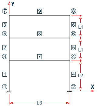
- L1 = 4.5 m
- L2 = 6 m
- L3 = 12 m
Actual input is shown in bold lettering followed by explanation.
STAAD PLANE FRAME WITH PRESTRESSING LOAD
Every input has to start with the term STAAD. The term PLANE signifies that the structure is a plane frame structure and the geometry is defined through X and Y axes.
UNIT METER KNS
Defines the input units for the data that follows.
    JOINT COORD
    1 0. 0. ; 2 12. 0. ; 3 0. 6. ; 4 12. 6.
    5 0. 10.5 ; 6 12. 10.5 ; 7 0. 15. ; 8 12. 15.
Joint number followed by X and Y coordinates are provided above. Since this is a plane structure, the Z coordinates need not be provided.
    MEMBER INCIDENCE
    1 1 3 ; 2 3 5 ; 3 5 7 ; 4 2 4 ; 5 4 6
    6 6 8 ; 7 3 4 ; 8 5 6 ; 9 7 8
Defines the members by the joints to which they are connected.
    SUPPORT
    1 2 FIXED
The supports at joints 1 and 2 are defined to be fixed supports.
    MEMB PROP
    1 TO 9 PRI AX 0.2044 IZ 8.631E-03
Member properties are provided using the PRI (prismatic) attribute. Values of area (AX) and moment of inertia about the major axis (IZ) are provided.
    UNIT MMS
    DEFINE MATERIAL START
    ISOTROPIC CONCRETE
    E 21.0
    POISSON 0.17
    DENSITY 2.36158e-008
    ALPHA 5e-006
    DAMP 0.05
    G 9.25
    TYPE CONCRETE
    STRENGTH FCU 0.0275
    END DEFINE MATERIAL
    CONSTANTS
    MATERIAL CONCRETE ALL
TThe DEFINE MATERIAL command is used to specify material properties and the CONSTANT is used to assign the material to all members. Length unit is changed from METER to MMS to facilitate the input.
    LOADING 1 PRESTRESSING LOAD
    MEMBER PRESTRESS
    7 8 FORCE 1350. ES 75. EM -300. EE 75.
Load case 1 is initiated followed by a title. Load 1 contains PRESTRESS load. Members 7 and 8 have a cable force of 1350 KNs. The location of the cable at the start (ES) and end (EE) is 75 MMs above the centre of gravity while at the middle (EM) it is 300 MMs below the c.g. The assumptions and facts associated with this type of loading are explained in G.15.5 Prestress and Poststress Member Load.
    LOADING 2 POSTSTRESSING LOAD
    MEMBER POSTSTRESS
    7 8 FORCE 1350. ES 75. EM -300. EE 75.
Load case 2 is initiated followed by a title. Load 2 is a POSTSTRESS load. Members 7 and 8 have a cable force of 1350 KNs. The location of the cable is the same as in load case 1. For a difference between PRESTRESS loading and POSTSTRESS loading, as well as additional information about both types of loads, please refer to G.15.5 Prestress and Poststress Member Load.
PERFORM ANALYSIS
This command instructs the program to perform the analysis.
    UNIT METER
    PRINT ANALYSIS RESULTS
The preceding command is an instruction to write joint displacements, support reactions and member forces in the output file. The preceding line causes the results to be written in the length unit of meters.
FINISH
This command terminates the STAAD run.
Input File
STAAD PLANE FRAME WITH PRESTRESSING LOAD
UNIT METER KNS
JOINT COORD
1 0. 0. ; 2 12. 0. ; 3 0. 6. ; 4 12. 6.
5 0. 10.5 ; 6 12. 10.5 ; 7 0. 15. ; 8 12. 15.
MEMBER INCIDENCE
1 1 3 ; 2 3 5 ; 3 5 7 ; 4 2 4 ; 5 4 6
6 6 8 ; 7 3 4 ; 8 5 6 ; 9 7 8
SUPPORT
1 2 FIXED
MEMB PROP
1 TO 9 PRI AX 0.2044 IZ 8.631E-03
UNIT MMS
DEFINE MATERIAL START
ISOTROPIC CONCRETE
E 21.0
POISSON 0.17
DENSITY 2.36158e-008
ALPHA 5e-006
DAMP 0.05
G 9.25
TYPE CONCRETE
STRENGTH FCU 0.0275
END DEFINE MATERIAL
CONSTANTS
MATERIAL CONCRETE ALL
LOADING 1 PRESTRESSING LOAD
MEMBER PRESTRESS
7 8 FORCE 1350. ES 75. EM -300. EE 75.
LOADING 2 POSTSTRESSING LOAD
MEMBER POSTSTRESS
7 8 FORCE 1350. ES 75. EM -300. EE 75.
PERFORM ANALYSIS
UNIT METER
PRINT ANALYSIS RESULTS
FINISH
STAAD Output File
                                                                  PAGE NO.    1
             ****************************************************
             *                                                  *
             *           STAAD.Pro CONNECT Edition              *
             *           Version  22.07.00.**                   *
             *           Proprietary Program of                 *
             *           Bentley Systems, Inc.                  *
             *           Date=    APR 19, 2021                  *
             *           Time=    17:27:25                      *
             *                                                  *
             *  Licensed to: Bentley Systems Inc                *
             ****************************************************
     1. STAAD PLANE FRAME WITH PRESTRESSING LOAD
INPUT FILE: UK-6 Prestress and Poststress Loading.STD
     2. UNIT METER KNS
     3. JOINT COORD
     4. 1 0. 0. ; 2 12. 0. ; 3 0. 6. ; 4 12. 6.
     5. 5 0. 10.5 ; 6 12. 10.5 ; 7 0. 15. ; 8 12. 15.
     6. MEMBER INCIDENCE
     7. 1 1 3 ; 2 3 5 ; 3 5 7 ; 4 2 4 ; 5 4 6
     8. 6 6 8 ; 7 3 4 ; 8 5 6 ; 9 7 8
     9. SUPPORT
    10. 1 2 FIXED
    11. MEMB PROP
    12. 1 TO 9 PRI AX 0.2044 IZ 8.631E-03
    13. UNIT MMS
    14. DEFINE MATERIAL START
    15. ISOTROPIC CONCRETE
    16. E 21.0
    17. POISSON 0.17
    18. DENSITY 2.36158E-008
    19. ALPHA 5E-006
    20. DAMP 0.05
    21. G 9.25
    22. TYPE CONCRETE
    23. STRENGTH FCU 0.0275
    24. END DEFINE MATERIAL
    25. CONSTANTS
    26. MATERIAL CONCRETE ALL
    27. LOADING 1 PRESTRESSING LOAD
    28. MEMBER PRESTRESS
    29. 7 8 FORCE 1350. ES 75. EM -300. EE 75.
    30. LOADING 2 POSTSTRESSING LOAD
    31. MEMBER POSTSTRESS
    32. 7 8 FORCE 1350. ES 75. EM -300. EE 75.
    33. PERFORM ANALYSIS
      FRAME WITH PRESTRESSING LOAD                             -- PAGE NO.    2
            P R O B L E M   S T A T I S T I C S
            -----------------------------------
     NUMBER OF JOINTS          8  NUMBER OF MEMBERS       9
     NUMBER OF PLATES          0  NUMBER OF SOLIDS        0
     NUMBER OF SURFACES        0  NUMBER OF SUPPORTS      2
           Using 64-bit analysis engine.
           SOLVER USED IS THE IN-CORE ADVANCED MATH SOLVER
   TOTAL      PRIMARY LOAD CASES =     2, TOTAL DEGREES OF FREEDOM =      18
   TOTAL LOAD COMBINATION  CASES =     0  SO FAR.
    34. UNIT METER
    35. PRINT ANALYSIS RESULTS
  ANALYSIS RESULTS
      FRAME WITH PRESTRESSING LOAD                             -- PAGE NO.    3
   JOINT DISPLACEMENT (CM   RADIANS)    STRUCTURE TYPE = PLANE
   ------------------
 JOINT  LOAD   X-TRANS   Y-TRANS   Z-TRANS   X-ROTAN   Y-ROTAN   Z-ROTAN
      1    1     0.0000    0.0000    0.0000    0.0000    0.0000    0.0000
           2     0.0000    0.0000    0.0000    0.0000    0.0000    0.0000
      2    1     0.0000    0.0000    0.0000    0.0000    0.0000    0.0000
           2     0.0000    0.0000    0.0000    0.0000    0.0000    0.0000
      3    1     0.1917    0.0000    0.0000    0.0000    0.0000    0.0004
           2     0.0000    0.0000    0.0000    0.0000    0.0000    0.0000
      4    1    -0.1917    0.0000    0.0000    0.0000    0.0000   -0.0004
           2     0.0000    0.0000    0.0000    0.0000    0.0000    0.0000
      5    1     0.1799    0.0000    0.0000    0.0000    0.0000    0.0008
           2     0.0000    0.0000    0.0000    0.0000    0.0000    0.0000
      6    1    -0.1799    0.0000    0.0000    0.0000    0.0000   -0.0008
           2     0.0000    0.0000    0.0000    0.0000    0.0000    0.0000
      7    1    -0.0014    0.0000    0.0000    0.0000    0.0000    0.0002
           2     0.0000    0.0000    0.0000    0.0000    0.0000    0.0000
      8    1     0.0014    0.0000    0.0000    0.0000    0.0000   -0.0002
           2     0.0000    0.0000    0.0000    0.0000    0.0000    0.0000
      FRAME WITH PRESTRESSING LOAD                             -- PAGE NO.    4
   SUPPORT REACTIONS -UNIT KNS  METE    STRUCTURE TYPE = PLANE
   -----------------
 JOINT  LOAD   FORCE-X   FORCE-Y   FORCE-Z     MOM-X     MOM-Y     MOM Z
      1    1    -30.59      0.00      0.00      0.00      0.00     80.49
           2      0.00      0.00      0.00      0.00      0.00      0.00
      2    1     30.59      0.00      0.00      0.00      0.00    -80.49
           2      0.00      0.00      0.00      0.00      0.00      0.00
      FRAME WITH PRESTRESSING LOAD                             -- PAGE NO.    5
   MEMBER END FORCES    STRUCTURE TYPE = PLANE
   -----------------
   ALL UNITS ARE -- KNS  METE     (LOCAL )
  MEMBER  LOAD  JT     AXIAL   SHEAR-Y  SHEAR-Z   TORSION     MOM-Y      MOM-Z
      1    1     1     -0.00     30.59     0.00      0.00      0.00      80.49
                 3      0.00    -30.59     0.00      0.00      0.00     103.07
           2     1      0.00      0.00     0.00      0.00      0.00       0.00
                 3      0.00      0.00     0.00      0.00      0.00       0.00
      2    1     3     -0.00     62.59     0.00      0.00      0.00     121.89
                 5      0.00    -62.59     0.00      0.00      0.00     159.77
           2     3      0.00      0.00     0.00      0.00      0.00       0.00
                 5      0.00      0.00     0.00      0.00      0.00       0.00
      3    1     5     -0.00     10.30     0.00      0.00      0.00      50.98
                 7      0.00    -10.30     0.00      0.00      0.00      -4.64
           2     5      0.00      0.00     0.00      0.00      0.00       0.00
                 7      0.00      0.00     0.00      0.00      0.00       0.00
      4    1     2      0.00    -30.59     0.00      0.00      0.00     -80.49
                 4     -0.00     30.59     0.00      0.00      0.00    -103.07
           2     2      0.00      0.00     0.00      0.00      0.00       0.00
                 4      0.00      0.00     0.00      0.00      0.00       0.00
      5    1     4      0.00    -62.59     0.00      0.00      0.00    -121.89
                 6     -0.00     62.59     0.00      0.00      0.00    -159.77
           2     4      0.00      0.00     0.00      0.00      0.00       0.00
                 6      0.00      0.00     0.00      0.00      0.00       0.00
      6    1     6      0.00    -10.30     0.00      0.00      0.00     -50.98
                 8     -0.00     10.30     0.00      0.00      0.00       4.64
           2     6      0.00      0.00     0.00      0.00      0.00       0.00
                 8      0.00      0.00     0.00      0.00      0.00       0.00
      7    1     3   1371.41   -168.75     0.00      0.00      0.00    -326.21
                 4  -1371.41   -168.75     0.00      0.00      0.00     326.21
           2     3   1339.41   -168.75     0.00      0.00      0.00    -101.25
                 4  -1339.41   -168.75     0.00      0.00      0.00     101.25
      8    1     5   1287.12   -168.75     0.00      0.00      0.00    -312.00
                 6  -1287.12   -168.75     0.00      0.00      0.00     312.00
           2     5   1339.41   -168.75     0.00      0.00      0.00    -101.25
                 6  -1339.41   -168.75     0.00      0.00      0.00     101.25
      9    1     7    -10.30     -0.00     0.00      0.00      0.00       4.64
                 8     10.30      0.00     0.00      0.00      0.00      -4.64
      FRAME WITH PRESTRESSING LOAD                             -- PAGE NO.    6
   MEMBER END FORCES    STRUCTURE TYPE = PLANE
   -----------------
   ALL UNITS ARE -- KNS  METE     (LOCAL )
  MEMBER  LOAD  JT     AXIAL   SHEAR-Y  SHEAR-Z   TORSION     MOM-Y      MOM-Z
           2     7      0.00      0.00     0.00      0.00      0.00       0.00
                 8      0.00      0.00     0.00      0.00      0.00       0.00
   ************** END OF LATEST ANALYSIS RESULT **************
    36. FINISH
             *********** END OF THE STAAD.Pro RUN ***********
               **** DATE= APR 19,2021   TIME= 17:27:26 ****
      FRAME WITH PRESTRESSING LOAD                             -- PAGE NO.    7
         ************************************************************
         *   For technical assistance on STAAD.Pro, please visit    *
         *   http://www.bentley.com/en/support/                     *
         *                                                          *
         *   Details about additional assistance from               *
         *   Bentley and Partners can be found at program menu      *
         *   Help->Technical Support                                *
         *                                                          *
         *           Copyright (c) Bentley Systems, Inc.            *
         *                http://www.bentley.com                    *
         ************************************************************