EX. UK-4 Inactive Members in a Braced Frame
This example is a typical case of a load-dependent structure where the structural condition changes for different load cases. In this example, different bracing members are made inactive for different load cases. This is done to prevent these members from carrying any compressive forces.
This problem is installed with the program by default to C:\Users\Public\Public Documents\STAAD.Pro CONNECT Edition\Samples\Sample Models\UK\UK-4 Inactive Members in a Braced Frame.STD when you install the program.
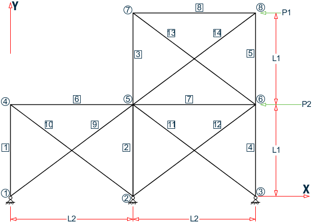
Example Problem No. 4
Where:
- L1 = 4.5 m, L2 = 6.0m
- P1 = 45 kN, P2 = 90 kN
Actual input is shown in bold lettering followed by explanation.
    STAAD PLANE
    * A PLANE FRAME STRUCTURE WITH TENSION BRACING
Every input has to start with the term STAAD. The term PLANE signifies that the structure is a plane frame structure and the geometry is defined through X and Y axes.
UNIT METER KNS
Defines the input units for the data that follows.
SET NL 3
This structure has to be analyzed for three primary load cases. Consequently, the modeling of our problem requires us to define three sets of data, with each set containing a load case and an associated analysis command. Also, the members which get switched off in the analysis for any load case have to be restored for the analysis for the subsequent load case. To accommodate these requirements, it is necessary to have two commands, one called SET NL and the other called CHANGE. The SET NL command is used above to indicate the total number of primary load cases that the file contains. The CHANGE command will come in later (after the PERFORM ANALYSIS command).
    JOINT COORDINATES
    1 0 0 0 3 12. 0. 0.
    4 0 4.5 0 6 12. 4.5 0.
    7 6. 9. 0. ; 8 12. 9. 0.
Joint number followed by X, Y and Z coordinates are provided above. Since this is a plane structure, the Z coordinates are given as all zeros.
    MEMBER INCIDENCE
    1 1 4 2 ; 3 5 7 ; 4 3 6 ; 5 6 8 ; 6 4 5 7
    8 7 8 ;  9 1 5 ; 10 2 4 ; 11 3 5 ; 12 2 6
    13 6 7 ; 14 5 8
Defines the members by the joints to which they are connected.
    MEMBER TRUSS
    9 TO 14
The preceding command defines that members 9 through 14 are of type truss. This means these members can only carry axial tension/compression and no moments.
    MEMBER PROP BRITISH
    1 TO 5 TABLE ST UB305X165X40
    6 7 8 TA ST UB457X152X52
    9 TO 14 TA LD UA150X150X10
Properties for all members are assigned from the British steel table. The word ST stands for standard single section. The word LD stands for long leg back-to-back double angle. Since the spacing between the two angles of the double angle is not provided, it is assumed to be 0.0.
    UNIT MMS
    DEFINE MATERIAL START
    ISOTROPIC STEEL
    E 210
    POISSON 0.3
    DENSITY 7.68191e-008
    ALPHA 6e-006
    DAMP 0.03
    TYPE STEEL
    STRENGTH FY 0.24821 FU 0.399894 RY 1.5 RT 1.2
    END DEFINE MATERIAL
    CONSTANTS
    MATERIAL STEEL ALL
The DEFINE MATERIAL command is used to define a material. The CONSTANT command is used to assign this material all members. Length unit is changed from METER to MMS.
    SUPPORT
    1 2 3 PINNED
Pinned supports are specified at Joints 1, 2 and 3. The word PINNED signifies that no moments will be carried by these supports.
INACTIVE MEMBERS 9 TO 14
The preceding command makes the listed members inactive. The stiffness contribution of these members will not be considered in the analysis till they are made active again.
    UNIT METER
    LOADING 1 DEAD AND LIVE LOAD
Load case 1 is initiated followed by a title. The length UNIT is changed from MMS to METER for input values which follow.
    MEMBER LOAD
    6 8 UNI GY -4.5
    7 UNI GY -6.75
Load 1 contains member loads. GY indicates that the load acts in the global Y direction. The word UNI stands for uniformly distributed load. The load is applied on members 6, 7, and 8.
PERFORM ANALYSIS
This command instructs the program to proceed with the analysis. It is worth noting that members 9 to 14 will not be used in this analysis since they were declared inactive earlier. In other words, for dead and live load, the bracing members are not used to carry any load.
CHANGES
The members inactivated earlier are restored using the CHANGE command.
INACTIVE MEMBERS 10 11 13
A new set of members are made inactive. The stiffness contribution from these members will not be used in the analysis till they are made active again. They have been inactivated to prevent them from being subject to compressive forces for the next load case.
LOADING 2 WIND FROM LEFT
Load case 2 is initiated followed by a title.
    JOINT LOAD
    4 FX 135 ; 7 FX 65
Load 2 contains joint loads. FX indicates that the load is a force in the global X direction. Nodes 4 and 7 are subjected to the loads.
PERFORM ANALYSIS
This command instructs the program to proceed with the analysis. The analysis will be performed for load case 2 only.
CHANGE
The above CHANGE command is an instruction to re-activate all inactive members.
INACTIVE MEMBERS 9 12 14
Members 9, 12 and 14 are made inactive. The stiffness contribution of these members will not be used in the analysis till they are made active again. They have been inactivated to prevent them from being subject to compressive forces for the next load case.
LOADING 3 WIND FROM RIGHT
Load case 3 is initiated followed by a title.
    JOINT LOAD
    6 FX -135 ; 8 FX -65
Load 3 contains joint loads at nodes 6 and 8. FX indicates that the load is a force in the global X direction. The negative numbers
(-135 and -65) indicate that the load is acting along the negative global X direction.
    LOAD COMBINATION 4
    1 0.75 2 0.75
    LOAD COMBINATION 5
    1 0.75 3 0.75
Load combination case 4 involves the algebraic summation of the results of load cases 1 and 2 after multiplying each by a factor of 0.75. For load combinations, the program simply gathers the results of the component primary cases, factors them appropriately, and combines them algebraically. Thus, an analysis in the real sense of the term (multiplying the inverted stiffness matrix by the load vector) is not carried out for load combination cases. Load combination case 5 combines the results of load cases 1 and 3.
PERFORM ANALYSIS
This command instructs the program to proceed with the analysis. Only primary load case 3 will be considered for this analysis. (As explained earlier, a combination case is not truly analyzed for, but handled using other means.)
CHANGE
The above CHANGE command will re-activate all inactive members.
LOAD LIST ALL
At the end of any analysis, only those load cases for which the analysis was done most recently, are recognized as the "active" load cases. The LOAD LIST ALL command enables all the load cases in the structure to be made active for further processing.
PRINT MEMBER FORCES
The preceding PRINT command is an instruction to produce a report, in the output file, of the member end forces.
LOAD LIST 1 4 5
A LOAD LIST command is a means of instructing the program to use only the listed load cases for further processing.
    PARAMETER
    CODE EN 1993-1-1:2005
    NA 1
    BEAM 1 ALL
    UNL 1.8 ALL
    KY 0.5 ALL
The PARAMETER command is used to specify the steel design parameters (information on these parameters can be obtained from the manual where the implementation of the code is explained). The BEAM parameter is specified to perform design at every 1/12th point along the member length. UNL represents the unsupported length to be used for calculation of allowable bending stress. KY 0.5 ALL sets the effective length factor for column buckling about the local Y-axis to be 0.5 for ALL members.
CHECK CODE ALL
The above command instructs the program to perform a check to determine how you defined member sizes along with the latest analysis results meet the code requirements.
FINISH
This command terminates the STAAD run.
Input File
STAAD PLANE A PLANE FRAME STRUCTURE WITH
* TENSION BRACING
UNIT METER KNS
SET NL 3
JOINT COORDINATES
1 0 0 0 3 12. 0. 0.
4 0 4.5 0 6 12. 4.5 0.
7 6. 9. 0. ; 8 12. 9. 0.
MEMBER INCIDENCE
1 1 4 2 ; 3 5 7 ; 4 3 6 ; 5 6 8 ; 6 4 5 7
8 7 8 ; 9 1 5 ; 10 2 4 ; 11 3 5 ; 12 2 6
13 6 7 ; 14 5 8
MEMBER TRUSS
9 TO 14
MEMBER PROP BRITISH
1 TO 5 TABLE ST UB305X165X40
6 7 8 TA ST UB457X152X52
9 TO 14 TA LD UA150X150X10
UNIT MMS
DEFINE MATERIAL START
ISOTROPIC STEEL
E 210
POISSON 0.3
DENSITY 7.68191e-008
ALPHA 6e-006
DAMP 0.03
TYPE STEEL
STRENGTH FY 0.24821 FU 0.399894 RY 1.5 RT 1.2
END DEFINE MATERIAL
CONSTANTS
MATERIAL STEEL ALL
SUPPORT
1 2 3 PINNED
INACTIVE MEMBERS 9 TO 14
UNIT METER
LOADING 1 DEAD AND LIVE LOAD
MEMBER LOAD
6 8 UNI GY -4.5
7 UNI GY -6.75
PERFORM ANALYSIS
CHANGES
INACTIVE MEMBERS 10 11 13
LOADING 2 WIND FROM LEFT
JOINT LOAD
4 FX 135 ; 7 FX 65
PERFORM ANALYSIS
CHANGE
INACTIVE MEMBERS 9 12 14
LOADING 3 WIND FROM RIGHT
JOINT LOAD
6 FX -135 ; 8 FX -65
LOAD COMBINATION 4
1 0.75 2 0.75
LOAD COMBINATION 5
1 0.75 3 0.75
PERFORM ANALYSIS
CHANGE
LOAD LIST ALL
PRINT MEMBER FORCES
LOAD LIST 1 4 5
PARAMETER
CODE EN 1993-1-1:2005
NA 1
BEAM 1 ALL
UNL 1.8 ALL
KY 0.5 ALL
CHECK CODE ALL
FINISH
STAAD Output File
PAGE NO. 1 **************************************************** * * * STAAD.Pro CONNECT Edition * * Version 22.07.00.** * * Proprietary Program of * * Bentley Systems, Inc. * * Date= APR 19, 2021 * * Time= 17:27:20 * * * * Licensed to: Bentley Systems Inc * **************************************************** 1. STAAD PLANE A PLANE FRAME STRUCTURE WITH INPUT FILE: UK-4 Inactive Members in a Braced Frame.STD 2. * TENSION BRACING 3. UNIT METER KNS 4. SET NL 3 5. JOINT COORDINATES 6. 1 0 0 0 3 12. 0. 0. 7. 4 0 4.5 0 6 12. 4.5 0. 8. 7 6. 9. 0. ; 8 12. 9. 0. 9. MEMBER INCIDENCE 10. 1 1 4 2 ; 3 5 7 ; 4 3 6 ; 5 6 8 ; 6 4 5 7 11. 8 7 8 ; 9 1 5 ; 10 2 4 ; 11 3 5 ; 12 2 6 12. 13 6 7 ; 14 5 8 13. MEMBER TRUSS 14. 9 TO 14 15. MEMBER PROP BRITISH 16. 1 TO 5 TABLE ST UB305X165X40 17. 6 7 8 TA ST UB457X152X52 18. 9 TO 14 TA LD UA150X150X10 19. UNIT MMS 20. DEFINE MATERIAL START 21. ISOTROPIC STEEL 22. E 210 23. POISSON 0.3 24. DENSITY 7.68191E-008 25. ALPHA 6E-006 26. DAMP 0.03 27. TYPE STEEL 28. STRENGTH FY 0.24821 FU 0.399894 RY 1.5 RT 1.2 29. END DEFINE MATERIAL 30. CONSTANTS 31. MATERIAL STEEL ALL 32. SUPPORT 33. 1 2 3 PINNED 34. INACTIVE MEMBERS 9 TO 14 35. UNIT METER 36. LOADING 1 DEAD AND LIVE LOAD 37. MEMBER LOAD 38. 6 8 UNI GY -4.5 A PLANE FRAME STRUCTURE WITH -- PAGE NO. 2 * TENSION BRACING 39. 7 UNI GY -6.75 40. PERFORM ANALYSIS P R O B L E M S T A T I S T I C S ----------------------------------- NUMBER OF JOINTS 8 NUMBER OF MEMBERS 14 NUMBER OF PLATES 0 NUMBER OF SOLIDS 0 NUMBER OF SURFACES 0 NUMBER OF SUPPORTS 3 Using 64-bit analysis engine. SOLVER USED IS THE IN-CORE ADVANCED MATH SOLVER TOTAL PRIMARY LOAD CASES = 1, TOTAL DEGREES OF FREEDOM = 18 TOTAL LOAD COMBINATION CASES = 0 SO FAR. 41. CHANGES 42. INACTIVE MEMBERS 10 11 13 43. LOADING 2 WIND FROM LEFT 44. JOINT LOAD 45. 4 FX 135 ; 7 FX 65 46. PERFORM ANALYSIS 47. CHANGE 48. INACTIVE MEMBERS 9 12 14 49. LOADING 3 WIND FROM RIGHT 50. JOINT LOAD 51. 6 FX -135 ; 8 FX -65 52. LOAD COMBINATION 4 53. 1 0.75 2 0.75 54. LOAD COMBINATION 5 55. 1 0.75 3 0.75 56. PERFORM ANALYSIS 57. CHANGE 58. LOAD LIST ALL 59. PRINT MEMBER FORCES MEMBER FORCES A PLANE FRAME STRUCTURE WITH -- PAGE NO. 3 * TENSION BRACING MEMBER END FORCES STRUCTURE TYPE = PLANE ----------------- ALL UNITS ARE -- KNS METE (LOCAL ) MEMBER LOAD JT AXIAL SHEAR-Y SHEAR-Z TORSION MOM-Y MOM-Z 1 1 1 11.15 -0.90 0.00 0.00 0.00 0.00 4 -11.15 0.90 0.00 0.00 0.00 -4.06 2 1 -1.07 0.78 0.00 0.00 0.00 -0.00 4 1.07 -0.78 0.00 0.00 0.00 3.49 3 1 68.16 -0.68 0.00 0.00 0.00 0.00 4 -68.16 0.68 0.00 0.00 0.00 -3.05 4 1 7.56 -0.09 0.00 0.00 0.00 -0.00 4 -7.56 0.09 0.00 0.00 0.00 -0.43 5 1 59.49 -1.18 0.00 0.00 0.00 0.00 4 -59.49 1.18 0.00 0.00 0.00 -5.33 2 1 2 51.94 -0.07 0.00 0.00 0.00 0.00 5 -51.94 0.07 0.00 0.00 0.00 -0.32 2 2 46.05 0.54 0.00 0.00 0.00 -0.00 5 -46.05 -0.54 0.00 0.00 0.00 2.41 3 2 129.15 -0.47 0.00 0.00 0.00 -0.00 5 -129.15 0.47 0.00 0.00 0.00 -2.09 4 2 73.50 0.35 0.00 0.00 0.00 -0.00 5 -73.50 -0.35 0.00 0.00 0.00 1.57 5 2 135.82 -0.40 0.00 0.00 0.00 -0.00 5 -135.82 0.40 0.00 0.00 0.00 -1.81 3 1 5 13.68 -2.95 0.00 0.00 0.00 -5.29 7 -13.68 2.95 0.00 0.00 0.00 -8.01 2 5 -0.99 1.45 0.00 0.00 0.00 3.48 7 0.99 -1.45 0.00 0.00 0.00 3.03 3 5 47.36 -2.44 0.00 0.00 0.00 -6.17 7 -47.36 2.44 0.00 0.00 0.00 -4.82 4 5 9.52 -1.13 0.00 0.00 0.00 -1.35 7 -9.52 1.13 0.00 0.00 0.00 -3.73 5 5 45.79 -4.05 0.00 0.00 0.00 -8.59 7 -45.79 4.05 0.00 0.00 0.00 -9.62 4 1 3 31.40 0.97 0.00 0.00 0.00 0.00 6 -31.40 -0.97 0.00 0.00 0.00 4.38 2 3 103.89 0.21 0.00 0.00 0.00 -0.00 6 -103.89 -0.21 0.00 0.00 0.00 0.93 3 3 -48.62 -0.59 0.00 0.00 0.00 0.00 6 48.62 0.59 0.00 0.00 0.00 -2.65 4 3 101.47 0.88 0.00 0.00 0.00 -0.00 6 -101.47 -0.88 0.00 0.00 0.00 3.98 5 3 -12.91 0.29 0.00 0.00 0.00 0.00 6 12.91 -0.29 0.00 0.00 0.00 1.29 A PLANE FRAME STRUCTURE WITH -- PAGE NO. 4 * TENSION BRACING MEMBER END FORCES STRUCTURE TYPE = PLANE ----------------- ALL UNITS ARE -- KNS METE (LOCAL ) MEMBER LOAD JT AXIAL SHEAR-Y SHEAR-Z TORSION MOM-Y MOM-Z 5 1 6 13.32 2.95 0.00 0.00 0.00 6.39 8 -13.32 -2.95 0.00 0.00 0.00 6.90 2 6 47.69 1.28 0.00 0.00 0.00 2.86 8 -47.69 -1.28 0.00 0.00 0.00 2.92 3 6 -1.29 -1.13 0.00 0.00 0.00 -2.15 8 1.29 1.13 0.00 0.00 0.00 -2.92 4 6 45.76 3.18 0.00 0.00 0.00 6.94 8 -45.76 -3.18 0.00 0.00 0.00 7.37 5 6 9.02 1.37 0.00 0.00 0.00 3.18 8 -9.02 -1.37 0.00 0.00 0.00 2.99 6 1 4 0.90 11.15 0.00 0.00 0.00 4.06 5 -0.90 15.85 0.00 0.00 0.00 -18.14 2 4 134.22 -1.07 0.00 0.00 0.00 -3.49 5 -134.22 1.07 0.00 0.00 0.00 -2.96 3 4 89.65 1.43 0.00 0.00 0.00 3.05 5 -89.65 -1.43 0.00 0.00 0.00 5.55 4 4 101.34 7.56 0.00 0.00 0.00 0.43 5 -101.34 12.69 0.00 0.00 0.00 -15.82 5 4 67.91 9.44 0.00 0.00 0.00 5.33 5 -67.91 10.81 0.00 0.00 0.00 -9.44 7 1 5 -1.98 22.41 0.00 0.00 0.00 23.75 6 1.98 18.09 0.00 0.00 0.00 -10.77 2 5 72.35 -1.12 0.00 0.00 0.00 -2.94 6 -72.35 1.12 0.00 0.00 0.00 -3.79 3 5 196.97 1.25 0.00 0.00 0.00 2.71 6 -196.97 -1.25 0.00 0.00 0.00 4.81 4 5 52.78 15.97 0.00 0.00 0.00 15.61 6 -52.78 14.41 0.00 0.00 0.00 -10.92 5 5 146.24 17.75 0.00 0.00 0.00 19.84 6 -146.24 12.63 0.00 0.00 0.00 -4.47 8 1 7 2.95 13.68 0.00 0.00 0.00 8.01 8 -2.95 13.32 0.00 0.00 0.00 -6.90 2 7 63.55 -0.99 0.00 0.00 0.00 -3.03 8 -63.55 0.99 0.00 0.00 0.00 -2.92 3 7 63.87 1.29 0.00 0.00 0.00 4.82 8 -63.87 -1.29 0.00 0.00 0.00 2.92 4 7 49.88 9.52 0.00 0.00 0.00 3.73 8 -49.88 10.73 0.00 0.00 0.00 -7.37 5 7 50.12 11.23 0.00 0.00 0.00 9.62 8 -50.12 9.02 0.00 0.00 0.00 -2.99 9 1 1 0.00 0.00 0.00 0.00 0.00 0.00 5 0.00 0.00 0.00 0.00 0.00 0.00 A PLANE FRAME STRUCTURE WITH -- PAGE NO. 5 * TENSION BRACING MEMBER END FORCES STRUCTURE TYPE = PLANE ----------------- ALL UNITS ARE -- KNS METE (LOCAL ) MEMBER LOAD JT AXIAL SHEAR-Y SHEAR-Z TORSION MOM-Y MOM-Z 2 1 -156.32 0.00 0.00 0.00 0.00 0.00 5 156.32 0.00 0.00 0.00 0.00 0.00 3 1 0.00 0.00 0.00 0.00 0.00 0.00 5 0.00 0.00 0.00 0.00 0.00 0.00 4 1 -117.24 0.00 0.00 0.00 0.00 0.00 5 117.24 0.00 0.00 0.00 0.00 0.00 5 1 0.00 0.00 0.00 0.00 0.00 0.00 5 0.00 0.00 0.00 0.00 0.00 0.00 10 1 2 0.00 0.00 0.00 0.00 0.00 0.00 4 0.00 0.00 0.00 0.00 0.00 0.00 2 2 0.00 0.00 0.00 0.00 0.00 0.00 4 0.00 0.00 0.00 0.00 0.00 0.00 3 2 -111.22 0.00 0.00 0.00 0.00 0.00 4 111.22 0.00 0.00 0.00 0.00 0.00 4 2 0.00 0.00 0.00 0.00 0.00 0.00 4 0.00 0.00 0.00 0.00 0.00 0.00 5 2 -83.41 0.00 0.00 0.00 0.00 0.00 4 83.41 0.00 0.00 0.00 0.00 0.00 11 1 3 0.00 0.00 0.00 0.00 0.00 0.00 5 0.00 0.00 0.00 0.00 0.00 0.00 2 3 0.00 0.00 0.00 0.00 0.00 0.00 5 0.00 0.00 0.00 0.00 0.00 0.00 3 3 -136.62 0.00 0.00 0.00 0.00 0.00 5 136.62 0.00 0.00 0.00 0.00 0.00 4 3 0.00 0.00 0.00 0.00 0.00 0.00 5 0.00 0.00 0.00 0.00 0.00 0.00 5 3 -102.46 0.00 0.00 0.00 0.00 0.00 5 102.46 0.00 0.00 0.00 0.00 0.00 12 1 2 0.00 0.00 0.00 0.00 0.00 0.00 6 0.00 0.00 0.00 0.00 0.00 0.00 2 2 -91.79 0.00 0.00 0.00 0.00 0.00 6 91.79 0.00 0.00 0.00 0.00 0.00 3 2 0.00 0.00 0.00 0.00 0.00 0.00 6 0.00 0.00 0.00 0.00 0.00 0.00 4 2 -68.84 0.00 0.00 0.00 0.00 0.00 6 68.84 0.00 0.00 0.00 0.00 0.00 5 2 0.00 0.00 0.00 0.00 0.00 0.00 6 0.00 0.00 0.00 0.00 0.00 0.00 13 1 6 0.00 0.00 0.00 0.00 0.00 0.00 7 0.00 0.00 0.00 0.00 0.00 0.00 2 6 0.00 0.00 0.00 0.00 0.00 0.00 7 0.00 0.00 0.00 0.00 0.00 0.00 A PLANE FRAME STRUCTURE WITH -- PAGE NO. 6 * TENSION BRACING MEMBER END FORCES STRUCTURE TYPE = PLANE ----------------- ALL UNITS ARE -- KNS METE (LOCAL ) MEMBER LOAD JT AXIAL SHEAR-Y SHEAR-Z TORSION MOM-Y MOM-Z 3 6 -76.79 0.00 0.00 0.00 0.00 0.00 7 76.79 0.00 0.00 0.00 0.00 0.00 4 6 0.00 0.00 0.00 0.00 0.00 0.00 7 0.00 0.00 0.00 0.00 0.00 0.00 5 6 -57.59 0.00 0.00 0.00 0.00 0.00 7 57.59 0.00 0.00 0.00 0.00 0.00 14 1 5 0.00 0.00 0.00 0.00 0.00 0.00 8 0.00 0.00 0.00 0.00 0.00 0.00 2 5 -77.83 0.00 0.00 0.00 0.00 0.00 8 77.83 0.00 0.00 0.00 0.00 0.00 3 5 0.00 0.00 0.00 0.00 0.00 0.00 8 0.00 0.00 0.00 0.00 0.00 0.00 4 5 -58.38 0.00 0.00 0.00 0.00 0.00 8 58.38 0.00 0.00 0.00 0.00 0.00 5 5 0.00 0.00 0.00 0.00 0.00 0.00 8 0.00 0.00 0.00 0.00 0.00 0.00 ************** END OF LATEST ANALYSIS RESULT ************** 60. LOAD LIST 1 4 5 61. PARAMETER 62. CODE EN 1993-1-1:2005 63. NA 1 64. BEAM 1 ALL 65. UNL 1.8 ALL 66. KY 0.5 ALL 67. CHECK CODE ALL STEEL DESIGN STAAD.PRO CODE CHECKING - BS EN 1993-1-1:2005 ******************************************** NATIONAL ANNEX - NA to BS EN 1993-1-1:2005 PROGRAM CODE REVISION V1.13 BS_EC3_2005/1 A PLANE FRAME STRUCTURE WITH -- PAGE NO. 7 * TENSION BRACING ALL UNITS ARE - KNS METE (UNLESS OTHERWISE Noted) MEMBER TABLE RESULT/ CRITICAL COND/ RATIO/ LOADING/ FX MY MZ LOCATION ======================================================================= *** WARNING:BEAM PARAM CHANGED FROM DEFAULT OF 3 DESIGN MIGHT NOT PROVIDE THE WORST CASE UTILIZATION FOR MEMBER 1 1 ST UB305X165X40 (BRITISH SECTIONS) PASS EC-6.3.3-662 0.097 5 59.49 C 0.00 -5.33 4.50 *** WARNING:BEAM PARAM CHANGED FROM DEFAULT OF 3 DESIGN MIGHT NOT PROVIDE THE WORST CASE UTILIZATION FOR MEMBER 2 2 ST UB305X165X40 (BRITISH SECTIONS) PASS EC-6.3.3-662 0.149 5 135.82 C 0.00 -1.81 4.50 *** WARNING:BEAM PARAM CHANGED FROM DEFAULT OF 3 DESIGN MIGHT NOT PROVIDE THE WORST CASE UTILIZATION FOR MEMBER 3 3 ST UB305X165X40 (BRITISH SECTIONS) PASS EC-6.3.3-662 0.112 5 45.79 C 0.00 -9.62 4.50 *** WARNING:BEAM PARAM CHANGED FROM DEFAULT OF 3 DESIGN MIGHT NOT PROVIDE THE WORST CASE UTILIZATION FOR MEMBER 4 4 ST UB305X165X40 (BRITISH SECTIONS) PASS EC-6.3.3-662 0.129 4 101.47 C 0.00 3.98 4.50 *** WARNING:BEAM PARAM CHANGED FROM DEFAULT OF 3 DESIGN MIGHT NOT PROVIDE THE WORST CASE UTILIZATION FOR MEMBER 5 5 ST UB305X165X40 (BRITISH SECTIONS) PASS EC-6.3.3-662 0.096 4 45.76 C 0.00 7.37 4.50 A PLANE FRAME STRUCTURE WITH -- PAGE NO. 8 * TENSION BRACING *** WARNING:BEAM PARAM CHANGED FROM DEFAULT OF 3 DESIGN MIGHT NOT PROVIDE THE WORST CASE UTILIZATION FOR MEMBER 6 6 ST UB457X152X52 (BRITISH SECTIONS) PASS EC-6.3.3-662 0.176 4 101.34 C 0.00 -15.82 6.00 *** WARNING:BEAM PARAM CHANGED FROM DEFAULT OF 3 DESIGN MIGHT NOT PROVIDE THE WORST CASE UTILIZATION FOR MEMBER 7 7 ST UB457X152X52 (BRITISH SECTIONS) PASS EC-6.3.3-662 0.241 5 146.24 C 0.00 19.84 0.00 *** WARNING:BEAM PARAM CHANGED FROM DEFAULT OF 3 DESIGN MIGHT NOT PROVIDE THE WORST CASE UTILIZATION FOR MEMBER 8 8 ST UB457X152X52 (BRITISH SECTIONS) PASS EC-6.3.3-662 0.096 5 50.12 C 0.00 9.62 0.00 *** WARNING:BEAM PARAM CHANGED FROM DEFAULT OF 3 DESIGN MIGHT NOT PROVIDE THE WORST CASE UTILIZATION FOR MEMBER 9 9 LD UA150X150X10 (BRITISH SECTIONS) PASS EC-6.2.3 (T) 0.085 4 117.24 T 0.00 0.00 0.00 *** WARNING:BEAM PARAM CHANGED FROM DEFAULT OF 3 DESIGN MIGHT NOT PROVIDE THE WORST CASE UTILIZATION FOR MEMBER 10 10 LD UA150X150X10 (BRITISH SECTIONS) PASS EC-6.2.3 (T) 0.061 5 83.41 T 0.00 0.00 0.00 *** WARNING:BEAM PARAM CHANGED FROM DEFAULT OF 3 DESIGN MIGHT NOT PROVIDE THE WORST CASE UTILIZATION FOR MEMBER 11 11 LD UA150X150X10 (BRITISH SECTIONS) PASS EC-6.2.3 (T) 0.074 5 102.46 T 0.00 0.00 0.00 *** WARNING:BEAM PARAM CHANGED FROM DEFAULT OF 3 DESIGN MIGHT NOT PROVIDE THE WORST CASE UTILIZATION FOR MEMBER 12 12 LD UA150X150X10 (BRITISH SECTIONS) PASS EC-6.2.3 (T) 0.050 4 68.84 T 0.00 0.00 0.00 A PLANE FRAME STRUCTURE WITH -- PAGE NO. 9 * TENSION BRACING *** WARNING:BEAM PARAM CHANGED FROM DEFAULT OF 3 DESIGN MIGHT NOT PROVIDE THE WORST CASE UTILIZATION FOR MEMBER 13 13 LD UA150X150X10 (BRITISH SECTIONS) PASS EC-6.2.3 (T) 0.042 5 57.59 T 0.00 0.00 0.00 *** WARNING:BEAM PARAM CHANGED FROM DEFAULT OF 3 DESIGN MIGHT NOT PROVIDE THE WORST CASE UTILIZATION FOR MEMBER 14 14 LD UA150X150X10 (BRITISH SECTIONS) PASS EC-6.2.3 (T) 0.042 4 58.38 T 0.00 0.00 0.00 ************** END OF TABULATED RESULT OF DESIGN ************** 68. FINISH *********** END OF THE STAAD.Pro RUN *********** **** DATE= APR 19,2021 TIME= 17:27:21 **** A PLANE FRAME STRUCTURE WITH -- PAGE NO. 10 * TENSION BRACING ************************************************************ * For technical assistance on STAAD.Pro, please visit * * http://www.bentley.com/en/support/ * * * * Details about additional assistance from * * Bentley and Partners can be found at program menu * * Help->Technical Support * * * * Copyright (c) Bentley Systems, Inc. * * http://www.bentley.com * ************************************************************