D5.C.6 Design Parameters
Design parameters communicate specific design decisions to the program. They are set to default values to begin with and may be altered to suite the particular structure.
Depending on the model being designed, you may have to change some or all of the parameter default values. Some parameters are unit dependent and when altered, the n setting must be compatible with the active "unit" specification.
The follow table lists all the relevant EC3 parameters together with description and default values.
| Parameter Name | Default Value | Description |
|---|---|---|
| CODE | - |
Must be specified as EN 1993-1-1:2005 to invoke design per Eurocode 3:2005 (EN 1993). 準拠する設計コード。「TR.48.1 パラメータの設定」を参照してください。 |
| ALH | 0.5 | The ratio of the distance of the point torque (from the start of the member) to the length of the member. The default value of 0.5 represents torque acting at the mid-span of a symmetrically loaded member. Values can range from 0 to 1. |
| ALPHA | 1.0 | Used to input a user defined value for the α factor in equation 6.41 for combined bending and axial force checks. |
| BEAM | 3 |
Parameter to control the number of sections to checked along the length of a beam:
|
| BETA | 1.0 | Used to input a user defined value for the β factor in equation 6.41 for combined bending and axial force checks. |
| C1 | 1.132 | Corresponds to the C1 factor to be used to calculate Elastic critical moment Mcr as per Clause 6.3.2.2 |
| C2 | 0.459 | Corresponds to the C2 factor to be used to calculate Elastic critical moment Mcr as per Clause 6.3.2.2 |
| C3 | 0 | Corresponds to the C3 factor to be used to calculate Elastic critical moment Mcr as per Clause 6.3.2.2 |
| CAN | 0 |
Member will be considered as a cantilever type member for deflection checks.
|
| CMM | 1.0 |
Indicates type of loading and support conditions on member. Used to calculate the C1, C2, and C3 factors to be used in the Mcr calculations. Can take a value from 1 to 8. Refer to Note 2 (below) for more information on its use. |
| CMN | 1.0 |
Indicates the level of End-Restraint.
|
| CMT | 1 |
Used to indicate the loading and support condition for torsion (ref. SCI publication P-057). Can take a value of 1-7. The values correspond to the various cases defined in section 6 and App. B of SCI-P-057. Refer to Note 4 (below) for more information |
| DFF | 0 (Mandatory for deflection check, TRACK 4) | "Deflection Length" / Max.. allowable local
deflection See Note 1d below. |
| DJ1 | Start Jointof member | Joint No. denoting starting point for calculation of "Deflection Length". See Note 1 below. |
| DJ2 | End Joint of member | Joint No. denoting end point for calculation of "Deflection Length". See Note 1 below. |
| DMAX | 100.0 cm | Maximum allowable depth for the member. |
| DMIN | 0 | Minimum required depth for the member. |
| EFT | Member Length | Effective length for torsion. A value of 0 defaults to the member length. |
| ELB | 0 |
Used to specify the method for combined axial load + bending checks
|
| ESTIFF | 0 |
(For use with the Dutch NA only) Method for checking columns forming part of (non)/buttressed framework:
Refer to D5.D.3.8 Clause 6.33 – Uniform members in bending and axial compression for additional description on this parameter. |
| FAB | 3 |
Used to specify the fabrication class to be used to check for slender (Class 4) CHS/pipe sections (EN 1993-1-6:2007)
|
| FU | 0 | Ultimate tensile strength of steel. |
| GM0 | 1.0 | Corresponds to the γm0 factor in EN 1993-1-1:2005 |
| GM1 | 1.0 | Corresponds to the γm1 factor in EN 1993-1-1:2005 |
| GM2 | 1.25 | Corresponds to the γm2 factor in EN 1993-1-1:2005 |
| GST | 0 |
Used to specify the section type to be used for designing a General Section from the user table. The member will be considered as the specified type with the user defined properties. The available options and corresponding values are as below:
|
| KC | 1.0 |
Corresponds to the correction factor as per Table 6.6 of EN 1993-1-1:2005. Program will calculate kc automatically if this parameter is set to 0. |
| KY | 1.0 | K factor in local y axis. Used to calculate the effective length for slenderness and buckling calculations. |
| KZ | 1.0 | K factor in local z axis. Used to calculate the effective length for slenderness and buckling calculations. |
| LEG | 0 |
Slenderness values for angles as determined from BS 5950-2000 Table 25. Refer to D3.B.6 Design Parameters |
| LVV | Max. value of Lyy | Leg length for Lvv (length about v-v- axis of single angle section), as per Lyy. Used for slenderness calculations. |
| LY | Member Length | Compression length in local y axis, Slenderness ratio = (KY)*(LY)/(Ryy) |
| LZ | Member Length | Compression length in local z axis, Slenderness ratio = (KZ)*(LZ)/(Rzz) |
| MTH | 0 |
Used to select the clause to be used to calculate the LTB reduction factor, χLT. The available options and corresponding values are as below:
By default, the program will use Cl 6.3.2.3 for rolled & built-up I-sections and Cl. 6.3.2.2 for all other sections. If, however, the specified National Annex expands on Cl. 6.3.2.3 to include other section types (e.g., the UK NA), the program will use Cl. 6.3.2.3 by default for that particular section type. Refer to D5.D. European Codes - National Annexes to Eurocode 3 [EN 1993-1-1:2005] for additional details on NA documents. |
| MU | 0 |
The ratio of the moment due to the transverse force to the maximum moment M. To be used with CMM values of 7 and 8. See Note 2 (below). |
| NA | 0 |
Choice of National Annex to be used for EC3 design. Refer to D5.D. European Codes - National Annexes to Eurocode 3 [EN 1993-1-1:2005] for values allowed for this parameter. (Refer to D5.C.1 General Description for more information) |
| NSF | 1.0 | Net tension factor for tension capacity calculation. |
| PLG | 0 |
To be used to determine whether to include the additional interaction checks as per CL. NA.20(2) and NA.20(3) of the Polish National Annex. |
| PY | Yield Strength | The yield strength default value is set based on the default value of the SGR parameter. |
| RATIO | 1 | Permissible ratio of loading to capacity. |
| SBLT | 0.0 |
Indicates if the section is rolled or built-up.
|
| SGR | 0 |
Steel grade as in Table 3.1: EN 1993-1-1: 2005:
|
| STIFF | Member Length or depth of beam, whichever is lesser | Distance between transverse stiffener plates, used to prevent web shear buckling. If not specified or if a value of 0 is provided, the program will assume the web is unstiffened. |
| TOM | 0 | Total torsion for design used for torsion checks. Can be used to override the total torsional moment to be used for member design. |
| TORSION | 0 |
Method to be used for a specific member or group of members:
|
| TRACK | 0 |
Specify level of detail in output.
|
| UNF | 1 | Unsupported length as a fraction of the actual member length. |
| UNL | Member Length | Unrestrained length of member used in calculating the lateral-torsional resistance moment of the member. |
| ZG | +Section Depth/2 |
Distance of transverse load from shear center. Used to calculate Mcr. |
Notes
-
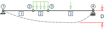
CAN, DJ1, and DJ2 – Deflection
-
When performing the deflection check, you can choose between two methods. The first method, defined by a value 0 for the CAN parameter, is based on the local displacement. 局所変位の詳細については、「TR.44 メンバーに関する断面変位の出力」を参照してください。.
If the CAN parameter is set to 1, the check will be based on cantilever style deflection. Let (DX1, DY1, DZ1) represent the nodal displacements (in global axes) at the node defined by DJ1 (or in the absence of DJ1, the start node of the member). Similarly, (DX2, DY2, DZ2) represent the deflection values at DJ2 or the end node of the member.
Compute Delta = SQRT((DX2 - DX1)2 + (DY2 - DY1)2 + (DZ2 - DZ1)2)
Compute Length = distance between DJ1 & DJ2 or, between start node and end node, as the case may be.
Then, if CAN is specified a value 1, dff = L/Delta
Ratio due to deflection = DFF/dff
-
If CAN = 0, deflection length is defined as the length that is used for calculation of local deflections within a member. It may be noted that for most cases the Deflection Length will be equal to the length of the member. However, in some situations, the Deflection Length may be different. A straight line joining DJ1 and DJ2 is used as the reference line from which local deflections are measured.
-
If DJ1 and DJ2 are not used, "Deflection Length" will default to the member length and local deflections will be measured from original member line.
-
It is important to note that unless a DFF value is specified, STAAD will not perform a deflection check. This is in accordance with the fact that there is no default value for DFF (see Table 2B.1).
-
The above parameters may be used in conjunction with other available parameters for steel design.
-
-
The values of CMM for various loading and support conditions are as given below:
Table 2. Values for the CMM Parameter CMM Value Loading and Support Conditions 1 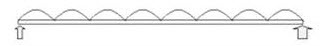
2 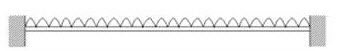
3 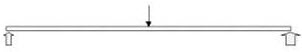
4 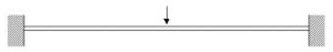
5 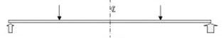
6 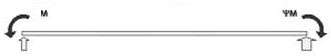
7 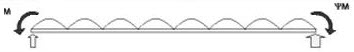
varying end moments and uniform loading
8 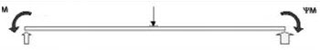
varying end moments and central point load
-
Checking beam deflection
With the TRACK parameter set to 4, the members included in a BEAM CHECK command will be checked for the local axis deflection rather than for the stress capacity using the current LOAD LIST.
If both stress capacity and deflection checks are required, then 2 parameter blocks with code checks are required, one with a TRACK 4 command and one with a TRACK 0, 1 or 2, thus:
LOAD LIST 1 TO 10
PARAMETER 1
CODE EN 1993
TRACK 2 ALL
CODE CHECK MEMBER 1
***************************
LOAD LIST 100 TO 110
PARAMETER 2
TRACK 4 ALL
DFF 300 MEMB 1
DJ1 1 MEMB 1
DJ2 4 MEMB 1
CHECK CODE MEMB 1
-
The values of CMT for various loading and support conditions are as given below:
Table 3. Loading and Support Conditions represented by CMT Parameter Values CMT Value
Description Diagram 1 (Default) : Concentrated Torque at Ends. Ends Torsion fixed and Warping fixed 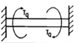
2 Concentrated Torque along length of member. Ends Torsion fixed and Warping free 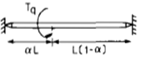
3 Concentrated Torque along length of member. Ends Torsion fixed and Warping fixed 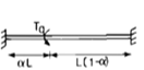
4 Uniform Torque in member. Ends Torsion fixed and Warping free 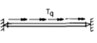
5 Uniform Torque in member. Ends Torsion fixed and Warping fixed 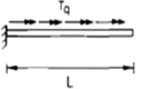
6 Concentrated Torque in cantilever. End Torsion fixed and Warping fixed 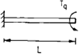
7 Uniform Torque in cantilever. End Torsion fixed and Warping fixed 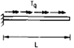 Note: For CMT = 2 and CMT = 3, you have the option of specifying the distance at which the concentrated torque acts, measured from the start of the member. This can be done by using the ALH design parameter. The ALH parameter indicates the ratio of the distance of the point torque (from the start of the member) to the length of the member. This parameter will have a default value of 0.5 (i.e., the torque acts at the center of the span) and will accept values ranging from 0 to 1.