V.API Overlapping K Joint - Tens and Bend
Verify the design of an overlapping K joint with axial load and in-plane bending.
References
Recommended Practice for Planning, Design and Constructing Fixed Offshore Platforms-Working Stress Design. American Petroleum Institute. 21st Edition (December 2000).
Details
Design of node 4 (between members 2 and 5) in the following model.
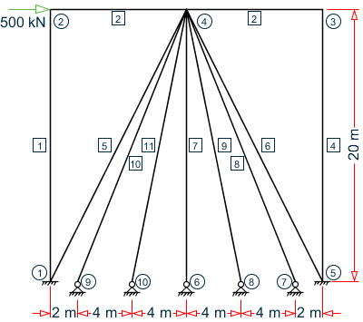
Chord member (2): D = 20 in, T = 1 in (Ac = 59.69 in2, Zc = 361.3 in3)
Brace member (5): d = 18 in, t = 1 in (Ab = 53.412, Zb = 289.33)
Brace member 10 overlaps with member 5.
Validation
Design Parameters
β = d/D = 0.9
So, 0.2 < β < 1.0 (OK)
γ = D/2T = 10
So, 10 < γ < 50 (OK)
θ = tan-1(10/5) = 63.4°
So, 30° < θ < 90° (OK)
Fy = 50 ksi (OK)
g = -4 mm
g/D = -4 / 20 = -0.2
Determination of Qu
First, evaluate Qg:
For g/D < -0.05: Qg = 0.13 + 0.65×ϕ×γ0.5 = 0.13 + 0.65×(1)×(10)0.5 = 2.185
Qu_ax = (16 + 1.2×γ)×β1.2×Qg = [16 + 1.2(10)](0.9)1.2(2.185) = 53.914
Qu_ipb = (5 + 0.7×γ)×β1.2 = [5 + 0.7(10)](0.9)1.2 = 10.575
Determination of Qf
From Table 4.3.2:
C1ax = 0.2, C2axi = 0.2, C3ax = 0.3
C1b = 0.2, C2b = 0, C3b = 0.4
Pyc = Ac×Fyc = 2,984.5 kips
Mpc = Zc×Fyc = 18,067 in·k
Pc = -499.21 kips
Mc = √ (MIPC2+MOPC2) = 268.18 in·k
Axial Capacity
Moment Capacity
Out-of-plane bending is zero so moment capacity is not calculated.
Brace Loads
As axial loads for through and overlapping braces are of different signs, the resultant axial load will be the sum of both brace loads (reference p.65).
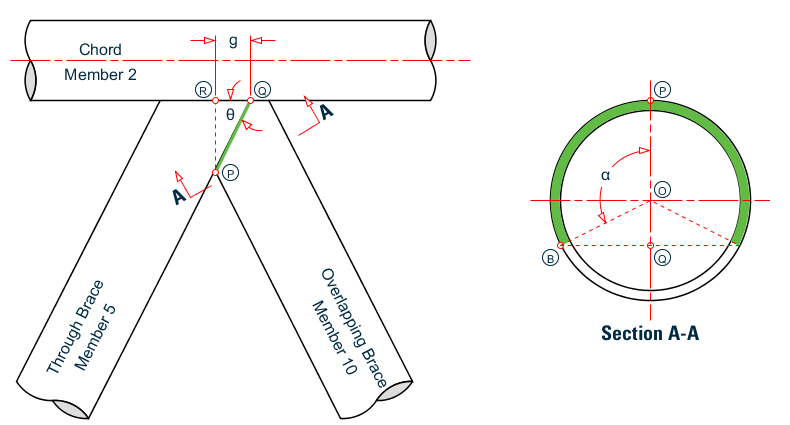
The gap distance, g = 4 in (segment QR).
Angle PQR = θ = 63.4°
The loaded segment length (green line PQ) = g/cos(θ) = 4/cos(63.4°) = 8.93 in
To determine the overlapping portion of the cross section of member 10 (i.e., the green portion of Section A-A), node that line segments OP and OB are equal to the radius of the pipe (use the nominal outer radius), r = 6 in.
cos(α) = (r - PQ)/r = (6 - 8.93) / 6 = -0.489
α = 119.3° = 2.082 rad
The arc length (green portion of Section A-A) = 2×α×r = 2(2.082)(6) = 25 in
The proportion of this arc to the total circumference = 25 / (2π×r) = 25 / (2π × 6) = 0.663
So the total axial load is the axial load of the through brace plus this ratio times the axial load of the overlapping brace (axial force values taken from STAAD.Pro post-processing workflow):
322.39 kip + 0.663 × 181.5 kip = 442.7 kip
According to p.65 of the API code, the resultant in-plane and out-plane bending moments will be algebraic summation of moments of the through brace and overlapping brace. Therefore, the total in-plane moment:
101.72 in·k + 12.61 in·k = 114.33 in·k
Interaction Ratio
P/Pa + (M/Ma)2 = (442.7 / 1,346.1) + (114.33 / 4,726)2 = 0.329
Results
| Result Type | Reference | STAAD.Pro | Difference | Comments |
|---|---|---|---|---|
| Qu_ax | 53.91 | 53.926 | negligible | |
| Qu_ipb | 10.575 | 10.575 | none | |
| Qf_ax | 0.893 | 0.893 | none | |
| Qf_ipb | 0.888 | 0.888 | none | |
| Axial capacity (kip) | 1,346.1 | 1,346.18 | negligible | |
| In-plane Bending Capacity (in·k) | 4,726 | 4,724.22 | negligible | |
| Brace Load, Axial (kip) | 442.7 | 442.72 | negligible | |
| Brace Load, In-plane Bending (in·k) | 114.33 | 114.33 | none | |
| Interaction ratio | 0.329 | 0.329 | none |
STAAD.Pro Input File
The file C:\Users\Public\Public Documents\STAAD.Pro CONNECT Edition\Samples\ Verification Models\09 Steel Design\US\API\API Overlapping KJoint - Tens and Bend.std is typically installed with the program.
STAAD SPACE
START JOB INFORMATION
ENGINEER DATE 12-Mar-19
END JOB INFORMATION
INPUT WIDTH 79
UNIT INCHES KIP
JOINT COORDINATES
1 0 0 0; 2 0 787.402 0; 3 787.402 787.402 0; 4 393.701 787.402 0;
5 787.402 0 0; 6 393.701 0 0; 7 708.661 0 0; 8 551.181 0 0; 9 78.7402 0 0;
10 236.22 0 0;
MEMBER INCIDENCES
1 1 2; 2 2 4; 3 4 3; 4 5 3; 5 1 4; 6 4 5; 7 4 6; 8 4 7; 9 4 8; 10 9 4; 11 10 4;
DEFINE MATERIAL START
ISOTROPIC STEEL
E 29732.7
POISSON 0.3
DENSITY 0.000283
ALPHA 1.2e-005
DAMP 0.03
TYPE STEEL
STRENGTH FY 36.7236 FU 59.1464 RY 1.5 RT 1.2
END DEFINE MATERIAL
MEMBER PROPERTY AMERICAN
1 TO 4 7 TABLE ST PIPE OD 20 ID 18
5 6 8 9 11 TABLE ST PIPE OD 18 ID 16
10 TABLE ST PIPE OD 12 ID 10
CONSTANTS
MATERIAL STEEL ALL
*START USER TABLE
*TABLE 1
*UNIT INCHES KIP
*PRISMATIC
*UPRISMATIC-PIPE(1)
*6.09218 280.735 280.735 561.471 3.04623 3.04623 20 20
*TABLE 2
*UNIT INCHES KIP
*PRISMATIC
*UPRISMATIC-PIPE(2)
*5.48931 205.369 205.369 410.738 2.74481 2.74481 18 18
*END
*DEFINE MATERIAL START
*ISOTROPIC ASTM_STEEL
*E 29000
*POISSON 0.3
*DENSITY 8.80613e-006
*ALPHA 2.16e-005
*DAMP 0.03
*G 11153.8
*END DEFINE MATERIAL
*MEMBER PROPERTY AMERICAN
*1 TO 4 7 UPTABLE 1 UPRISMATIC-PIPE(1)
*5 6 8 TO 11 UPTABLE 2 UPRISMATIC-PIPE(2)
*CONSTANTS
*MATERIAL ASTM_STEEL ALL
SUPPORTS
1 5 FIXED
6 TO 10 PINNED
DEFINE REFERENCE LOADS
LOAD R1 LOADTYPE Dead  TITLE LOAD GROUP 1
JOINT LOAD
2 FX 500
END DEFINE REFERENCE LOADS
LOAD 1 LOADTYPE Dead  TITLE LOAD CASE 1
REFERENCE LOAD
R1 1.0
PERFORM ANALYSIS
PRINT MEMBER PROPERTIES ALL
PARAMETER 1
CODE API
FYLD 50 ALL
FSJ 2 MEMB 2 3 5 6 8 10
TRACK 2 MEMB 2 3 5 6 8 10
CHECK CODE MEMB 2 3 5 6 8 10
FINISH
STAAD.Pro Output
          STAAD.Pro - API JOINT CHECKS TO 21st edition.
          ---------------------------------------------------
                     (Includes Supplements 1-3)
          ---------------------------------------------------
======================================================================
NODE NO :      4   CHORD NO:     2   BRACE NO:     5
======================================================================
DESIGN DATA : (Units    : kip,inch)
  Chord Memb :      D =   20.00  T =  1.00
  Brace Memb :      d =   18.00  t =  1.00
  Angle (THETA) =  63.4 deg  GAP   =   -4.00   Fyc =  50.0
  BETA          =  0.90      GAMMA =   10.00   TAU =  1.00
      ***WARNING - JNT      4: OVERLAP
      OVERLAP PROVIDED =   4.00 IS LESS THAN THE NOMINAL VALUE OF 0.25*BETA*D.
JOINT CLASS :          KO
  Overlap Brace :      10   Angle =   68.20 deg.   Diam. =   12.00
  FACTORS :
  --------------------------------------------------------------------
  Joint   Load   Strength     Chord Load    C1        C2        C3
  Class   Cond   factor (Qu)  factor (Qf)
  --------------------------------------------------------------------
    K     AX      53.926        0.893       0.200    0.200    0.300
    K     IPB     10.575        0.888       0.200    0.000    0.400
----------------------------------------------------------------------
CAPACITY CHECKS        BRACE LOAD    LC   CAPACITY   RATIO   STATUS
   (Cl. 4.3)             (kip,in)         (kip,in)
----------------------------------------------------------------------
AXIAL        :            442.72      1     1346.18    0.329   PASS
IP BENDING   :            114.33      1     4724.22    0.024   PASS
INTERACTION  :                        1                0.329   PASS
----------------------------------------------------------------------
CRITICAL     :                        1                0.329   PASS
----------------------------------------------------------------------