G.6.6 Steel Joist and Joist Girders
Member properties can be assigned by specifying a joist designation contained in tables supplied with the program. The following joists and joist girder types have been implemented:
- Open web steel joists – K series and KCS joists
- Longspan steel joists – LH series
- Deep Longspan steel joists – DLH series
- Joist Girders – G series
The designation for the G series Joist Girders is as shown in the Steel Joist Institute publication. STAAD.Pro incorporates the span length also in the name, as shown in the next figure.
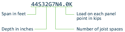
STAAD.Pro nomenclature for SJI joist girders
Theoretical basis for modeling the joist
Steel joists are prefabricated, welded steel trusses used at closely spaced intervals to support floor or roof decking. Thus, from an analysis standpoint, a joist is not a single member in the same sense as beams and columns of portal frames that one is familiar with. Instead, it is a truss assembly of members. In general, individual manufacturers of the joists decide on the cross section details of the members used for the top and bottom chords, and webs of the joists. So, joist tables rarely contain any information on the cross-section properties of the individual components of a joist girder. The manufacturer’s responsibility is to guarantee that, no matter what the cross section details of the members are, the joist simply has to ensure that it provides the capacity corresponding to its rating.
The absence of the section details makes it difficult to incorporate the true truss configuration of the joist in the analysis model of the overall structure. In STAAD, selfweight and any other member load applied on the joist is transferred to its end nodes through simply supported action. Also, in STAAD, the joist makes no contribution to the stiffness of the overall structure.
- The entire joist is represented in the STAAD input file by a single member. Graphically it will be drawn using a single line.
- After creating the member, the properties should be assigned from the joist database.
- The 3D Rendering feature of the program will display those members using a representative Warren type truss.
- The intermediate span-point displacements of the joist cannot be determined.
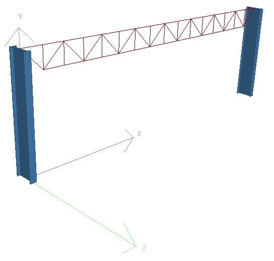
Example rendering of a joist member in STAAD.Pro
Assigning the joists
The procedure for assigning the joists is explained in the Graphical User Interface manual.
The STAAD joists database includes the weight per length of the joists. So, for selfweight computations in the model, the weight of the joist is automatically considered.
Example
An example of a structure with joist (command file input data) is shown below.
STAAD SPACE EXAMPLE FOR JOIST GIRDER
UNIT FEET KIP
JOINT COORDINATES
1 0 0 0; 2 0 10 0
3 30 10 0; 4 30 0 0
MEMBER INCIDENCES
1 1 2; 2 2 3; 3 3 4;
MEMBER PROPERTY AMERICAN
1 3 TABLE ST W21x50
MEMBER PROPERTY SJIJOIST
2 TABLE ST 22K6
CONSTANTS
E STEEL ALL
DENSITY STEEL ALL
POISSON STEEL ALL
SUPPORTS
1 4 FIXED
UNIT POUND FEET
LOAD 1
SELFWEIGHT Y -1
LOAD 2
MEMBER LOAD
2 UNI GY -250
LOAD COMB 3
1 1 2 1
PERF ANALY PRINT STAT CHECK
PRINT SUPP REAC
FINISH