TR.28.2.2 Check Irregularities
STAAD.Pro can check irregularities per the IS 1893 2016 and ASCE 7-05/10/16 seismic codes.
For IS 1893 2016, the program can check horizontal irregularities (torsional and reentrant corners) per Table 5 and vertical irregularities (mass irregularities and irregular modes of oscillation) per Table 6.
For ASCE 7-05/10/16, the program can check horizontal irregularities (torsional and reentrant corners) and vertical irregularies (mass). Irregular modes of oscillation are not considered for this code.
Torsion Check per ASC 7
Torsion checks per Cl. 12.3.2.1 of ASCE 7 2016 ( ref. fig C12.3-1 Type 1) are preformed by applying unit loads in each orthogonal direction to the master node of the diaphragm.
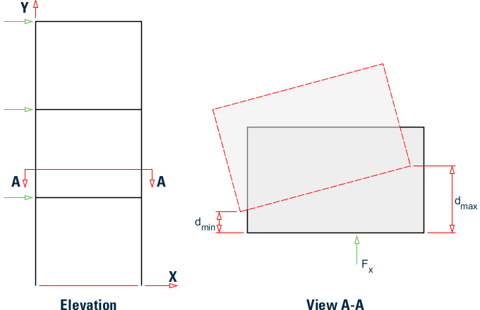
The unit load, Fx, is applied at each diaphragm in the X-direction. After analysis, the program locates the extreme nodes of the diaphragm and then dmin and dmax are calculated. The ratio of dmax/dmin is evaluated and compared to the code limit of 1.5. This process is then repeated in the Z direction for this diaphragm. Then the similar process is applied to the other diaphragms in the structure.
Torsion Check per IS 1893
Torsion checks per Table 5(i)-a IS 1893 2016 are performed by applying a unit force in each orthogonal direction at two different distances (the design eccentricity, edi) as per Cl. 7.8.2. This results in evaluating four different conditions for IS 1893 2016. The analysis is run and the displacements of the two extreme ends of the diaphragm are extracted from the analysis results. This ratio of these displacements is then checked against the code limit of 1.5.
| (Design eccentricity per IS 1893 2016 Cl. 7.8.2) |
| = | ||
| = |
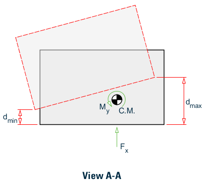
Example floor diaphragm torsion for IS 1893
The unit load, Fx is applied at each diaphragm in the X-direction in combination with two cases of My = Fx× (edi - esi) representing the to cases for edi. After analysis, the program locates the extreme nodes of the diaphragm and then dmin and dmax are calculated. The ratio of dmax/dmin is evaluated and compared to the code limit of 1.5. This process is then repeated in the Z direction for this diaphragm for a total of four cases at each diaphragm. Then the similar process is applied to the other diaphragms in the structure.
Reentrant Corners
The program will check for reentrant corners per Table 5(ii) of IS 1893 2016 and Cl. 12.3.2.1 of ASCE 7 2016 ( ref. fig C12.3-1 Type 2). The program first automatically identifies the boundary topology of the diaphragm. That is, the order in which analytical members and nodes of the boundary of the diaphragm are joined together to for a closed polygon. The program then determines the reentrant, or concave, corners of the diaphragm. The two analytical members joining the reentrant node is determined, their lengths are calculated, and then the projections of those lengths are calculated. To determine the ratios, the following are calculated:
Li×cos(α)/Lx ≤ 0.15
Li×cos(α)/Lz ≤ 0.15
If both members from the reentrant node are orthogonal, then for each member, only 1 ratio is calculated as Li/Lx for members oriented along the x-direction and Li/Lz for members oriented along the z-direction.
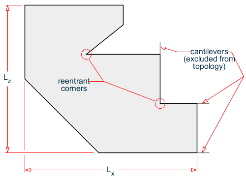
Example reentrant corner topology
All slave nodes that form part of a diaphragm must lie within the same plane. Further, the boundary slave nodes must form a closed polygon. Improper modeling of diaphragms may yield incorrect irregularity status results.
Mass Irregularities
The program will check for mass irregularities per Table 6(ii) of IS 1893 2016 and Cl. 12.3.2.2 of ASCE 7 2016 (ref. fig C12.3-2 Type 2). The mass of each floor is calculated as the total of all floor diaphragm masses at the same level. The ratio of each floor mass to the floor above and below is calculated. These ratios are compared to the code stipulated values.
Irregular Modes of Oscillation
Per Table 6(vii)-a, the sum of the percentage of mass participation for the first 3 modes should be greater than 65%. This is checked in both orthogonal directions.
Per Table 6(vii)-b, the time period for the fundamental modes in one direction should differ by at least 10%.
IS 1893 2016 Example
An example using IS 1893 2016:
FLOOR DIAPHRAGM
DIA 1 TYPE RIG HEI 3
DIA 2 TYPE RIG HEI 6
DIA 3 TYPE RIG HEI 9
CHECK IRREGULARITIES CODE IS1893 2016
ASCE 7 Example
An example using ASCE 7:
FLOOR DIAPHRAGM
DIA 1 TYPE RIG HEI 0
DIA 2 TYPE RIG HEI 5
CHECK IRREGULARITIES CODE ASCE7
IS 1893 2016 Example Output
An example output section of an IS 1893 2016 seismic irregularities check:
-IRREGULARITY CHECKS

                    STAAD.PRO IRREGULARITIES CHECK - (  IS1893-2016  )   v1.0
                    *****************************************************

 --TORSION IRREGULARITY CHECKS

 Torsion Irregularity Check
 Ref: Table 5 (i)    - Ratio Limit: 1.50
 ---------------------------------------

 Dia.   Extreme Points of Dia in X        Extreme Points of Dia in Z
       Node    Disp.    Node    Disp.    Node    Disp.     Node    Disp.
               (mm)             (mm)             (mm)              (mm)
 ------------------------------------------------------------------------
    1     12   0.04678      6   0.04678      2   0.04678      8   0.04678
    2     36   0.13804     30   0.13804     26   0.13804     32   0.13804

             Diaphragm DX-max/min DZ-max/min Status
             --------------------------------------
                   1     1.0000   1.0000        OK
                   2     1.0000   1.0000        OK
 --GEOMETRY IRREGULARITY CHECKS

 Re-Entrant Corner Check.
 (Ref: Table 5 (ii)   - Ratio Limit: 0.15 )
 ------------------------------------------

     Node      Re-Entrant X-Proj  X-Proj/Lx Z-Proj  Z-Proj/Lz  Status
  Connectivity     Node    ( m)              ( m)
 ----------------------------------------------------------------------
         2->         1      4.0000  0.3333    0.0000  0.0000 Re-Entrant
         5                  0.0000  0.0000    4.0000  0.3333
         6->         7      0.0000  0.0000    4.0000  0.3333 Re-Entrant
         8                  4.0000  0.3333    0.0000  0.0000
         9->        10      4.0000  0.3333    0.0000  0.0000 Re-Entrant
        11                  0.0000  0.0000    4.0000  0.3333
        12->         4      0.0000  0.0000    4.0000  0.3333 Re-Entrant
         3                  4.0000  0.3333    0.0000  0.0000
        26->        25      4.0000  0.3333    0.0000  0.0000 Re-Entrant
        29                  0.0000  0.0000    4.0000  0.3333
        30->        31      0.0000  0.0000    4.0000  0.3333 Re-Entrant
        32                  4.0000  0.3333    0.0000  0.0000
        33->        34      4.0000  0.3333    0.0000  0.0000 Re-Entrant
        35                  0.0000  0.0000    4.0000  0.3333
        36->        28      0.0000  0.0000    4.0000  0.3333 Re-Entrant
        27                  4.0000  0.3333    0.0000  0.0000

                   Diaphragm:    Lx:       Lz:
                                 ( m)     ( m)
                   ----------------------------
                        1     12.0000   12.0000
                        2     12.0000   12.0000
 --MASS IRREGULARITY CHECKS

 Mass Irregularity Check
 Ref: Table 6 (ii)   - Ratio Limit: 1.50
 ---------------------------------------

 Dia.   Level     Mass       Above      Below     Ratio  Ratio  Status
        ( m)      ( kN)      ( kN)      ( kN)     Above  Below
 ---------------------------------------------------------------------
    1     0.000    636.163    459.451    Base      1.385   N/A     OK
    2     5.000    459.451    Top        636.163    N/A   0.722    OK

   ***NOTE: Linear dynamic analysis needs to carried out for Irregular
   Modes of Oscillation check.

   ***NOTE: Static Seismic Loads for relevant code needs to be defined
   with Zone 4 and 5 for Irregular Modes of Oscillation  check.
ASCE 7 Example Output
An example output section of an ASCE 7-2016 seismic irregularities check:
                    STAAD.PRO IRREGULARITIES CHECK - (  ASCE7-2016   )   v1.0
                    *****************************************************

 --TORSION IRREGULARITY CHECKS

 Torsion Irregularity Check
 Ref: Fig. C12.3-1 T1- Ratio Limit(s): 1.20, 1.40
 ------------------------------------------------

 Dia.   Extreme Points of Dia in X        Extreme Points of Dia in Z
       Node    Disp.    Node    Disp.    Node    Disp.     Node    Disp.
               (mm)             (mm)             (mm)              (mm)
 ------------------------------------------------------------------------
    1      3   0.09130      1   0.09993      4   0.09484      1   0.10559
    2     15   0.29636     13   0.30993     16   0.29819     13   0.34410

             Diaphragm ΔX-max/avg ΔZ-max/avg Status
             --------------------------------------
                   1     1.0451   1.0537        OK
                   2     1.0224   1.0715        OK
 --GEOMETRY IRREGULARITY CHECKS

 Re-Entrant Corner Check.
 (Ref: Fig. C12.3-1 T2- Ratio Limit: 0.15 )
 ------------------------------------------

     Node      Re-Entrant X-Proj  X-Proj/Lx Z-Proj  Z-Proj/Lz  Status
  Connectivity     Node    ( m)              ( m)
 ----------------------------------------------------------------------
         6->         5      0.0000  0.0000    7.0000  0.7778 Re-Entrant
         4                  1.0000  0.2000    0.0000  0.0000
        18->        17      0.0000  0.0000    7.0000  0.7778 Re-Entrant
        16                  1.0000  0.2000    0.0000  0.0000

                   Diaphragm:    Lx:       Lz:
                                 ( m)     ( m)
                   ----------------------------
                        1      5.0000    9.0000
                        2      5.0000    9.0000
 --MASS IRREGULARITY CHECKS

 Mass Irregularity Check
 Ref: Fig. C12.3-2 T2- Ratio Limit: 1.50
 ---------------------------------------

 Dia.   Level     Mass       Above      Below     Ratio  Ratio  Status
        ( m)      ( kN)      ( kN)      ( kN)     Above  Below
 ---------------------------------------------------------------------
    1     0.000    341.643    253.287    Base      1.349   N/A     OK
    2     5.000    253.287    Top        341.643    N/A   0.741    OK