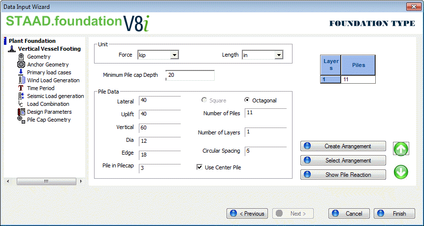
| Unit |
Choose Units for force and length, these units are only applicable to Pile Cap Geometry Page. |
| Minimum Pile cap Depth |
|
|
Lateral
|
Specify the lateral capacity of a pile.
|
|
Vertical
|
Specify the vertical capacity of a pile.
|
|
Uplift
|
Specify the uplifting capacity of a pile.
|
|
Dia
|
Diameter of a pile.
|
|
Edge
|
The Edge Distance field allows you to specify the distance between the edges of a pile.
|
| Pile Data group |
Type values for Lateral, Uplift, Vertical capacities of pile from geotechnical report. |
| Arrangement Type |
Pile arrangement can be either rectangular or circular. Pile cap having circular arrangement will be design as octagonal pile cap. For octagonal foundation, pile arrangement is automatically set as circular.
Rectangular arrangement needs following inputs,
- Number of Rows - Usually for vertical vessel foundation, pile cap is kept as square pile cap. To do so, enter same number of rows and column with same row and column spacing.
- Number of Columns
- Row Spacing
- Column Spacing
By default program will create symmetric pile arrangement from the above input but user can change the default setup by editing the table below. Both row and column grid lines can be adjusted by selecting appropriate radio button.
Circular arrangement needs following inputs as shown below.
- Number of Piles – Total number of piles, excluding the center pile (if option is selected).
- Number of Layers – Number of concentric circles in the circular arrangement.
- Pile Spacing – Minimum spacing between piles
- Use Center Pile – Select this option to add a pile at center of pile arrangement.
By default, program will try to assign equal number of piles for all concentric circular layers. The arrangement can be edited using the table below.
|
|
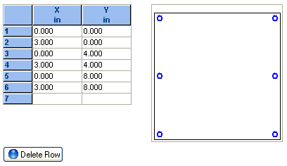
Create Pile Arrangement
|
Creates the pile layout and opens a dialog box to display the pile coordinates table and a figure.
Note: Pile coordinates in this table are editable.
Delete Row - Click to delete the current row from the pile coordinate table and figure.
|
|
Select Arrangement
|
Once a satisfactory pile layout has been found, click the Select Current Arrangement button to select and apply that layout.
The program will check the pile reaction against pile capacity to make sure pile reactions do not exceed pile capacity values.
|
|
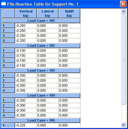
Show Pile Reactions
|
The Show Pile Reactions button opens a table displaying the reaction on each pile. The figure below shows the pile reaction table.
Note: To get the pile reaction, the file needs to be run once. Once you have designed the Vertical Vessel Foundation job, select Vertical Vessel Footing > Edit to return to this page to view the Pile Reaction table.
|
| spacing type and table |
Once a pile arrangement is started, the table displays the spacing for each row, column, layer, or circumference; depending on what arrangement type and table spacing type is selected. |